TFT Modules for Embedded Display Integration
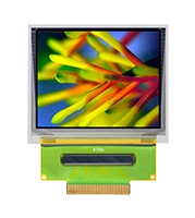
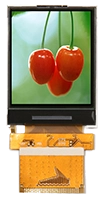
TFT modules are display assemblies built around a thin-film transistor liquid crystal display (TFT LCD) panel. Depending on the model, a module may include a backlight, driver circuitry, and a flexible circuit connection. Touch sensors, cover glass, and controller boards may be separate options. Define the assembly you need before comparing dimensions or prices, since two products described as modules can include different parts.
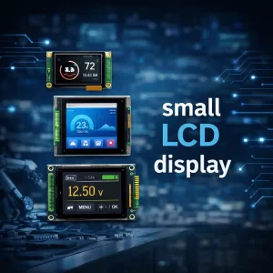
For hardware engineers and product designers, selection starts with the device interface and the conditions in which people will read the screen. A handheld instrument needs a compact assembly with manageable power consumption. A wall-mounted controller may place more emphasis on viewing angle, front appearance, and access to the display connector during assembly.
Match the Electrical Interface to the Host
Choose TFT modules against the actual display outputs available on the processor or host board. With RGB TFT displays, check the data width, signal voltage, pixel clock, and synchronization timing. Confirm that the host can continuously supply pixel data at the required rate. A matching resolution alone does not establish electrical or timing compatibility.
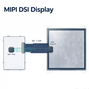
For LVDS TFT displays, compare the channel count, data mapping, and connector pinout. MIPI TFT displays need a compatible DSI host, a suitable lane configuration, and software that supports the panel’s initialization requirements. Check the exact part number and revision against the board documentation before connecting a sample. The connector shape and pin count give only part of the information needed.
Judge the Image Through the Final Front Assembly
Evaluate brightness, contrast, and viewing angle with the intended user interface on screen. Small gray labels may be difficult to read even when a bright test image looks acceptable. Position the sample at the planned mounting angle and inspect it under representative lighting. Include the cover glass or touch assembly, since reflections from the front surface affect what the user can see.
When comparing TFT modules for a battery-powered device, include the backlight in the power budget. Test the brightness level the application actually needs and measure consumption at that setting. For enclosed equipment, check temperature with the display and host operating together. A brighter backlight can improve visibility in some environments while adding heat that the housing must dissipate.
Check Fit, Handling, and Replacement Requirements
Use the mechanical drawing to compare the active area, viewing area, module outline, thickness, and mounting provisions. Leave room for the flexible circuit and its bend where it enters the host connector. Verify the insertion direction and cable access with the intended assembly sequence. A connector that is accessible on a bench may be blocked after the board and screen are installed.
For a touchscreen product, specify whether the touch sensor and cover lens are supplied with the display and how the complete assembly will be supported. Keep mounting loads away from areas that the supplier identifies as sensitive to pressure. Before approving a replacement, compare the new module’s electrical, optical, and mechanical details with the approved version, then repeat image and touch tests using the production firmware and enclosure.