When designing TFT LCD or touch modules, engineers often ask: Should I use FPC or FFC? At first glance, it seems like a simple cable choice. FPC looks integrated and compact, while FFC appears modular and easy to connect using standard connectors. However, this decision is not just about cables — it is fundamentally an electrical and architectural question determined by the display interface.
In this article, we will clarify the differences FPC vs FFC, explain why FPC is often necessary, when FFC can be used, and provide practical guidance for engineers evaluating TFT LCD interconnect solutions.
Should You Use FPC or FFC?
Many engineers initially treat the decision as a mechanical selection:
- “Which cable is thinner?”
- “Which one is easier to assemble?”
- “Which one is cheaper?”
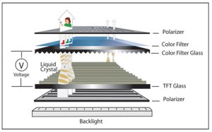
This surface-level thinking misses the real challenge. In TFT LCD and touch modules, the critical factor is display interface architecture:
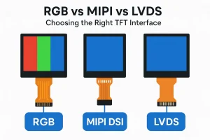
- Interfaces such as RGB, LVDS, or MIPI DSI have specific electrical requirements.
- These requirements dictate how signals, power, and ground planes must be routed.
- The cable alone cannot satisfy high-speed signal integrity — the interconnect must be part of the engineered solution.
Key insight: The choice of FPC vs FFC is rarely about the cable itself. It is about how the module integrates the display interface and delivers signals reliably to the mainboard.
Basic Understanding: What Are FPC and FFC?
Before we dive into module architecture, it is crucial to align terminology.
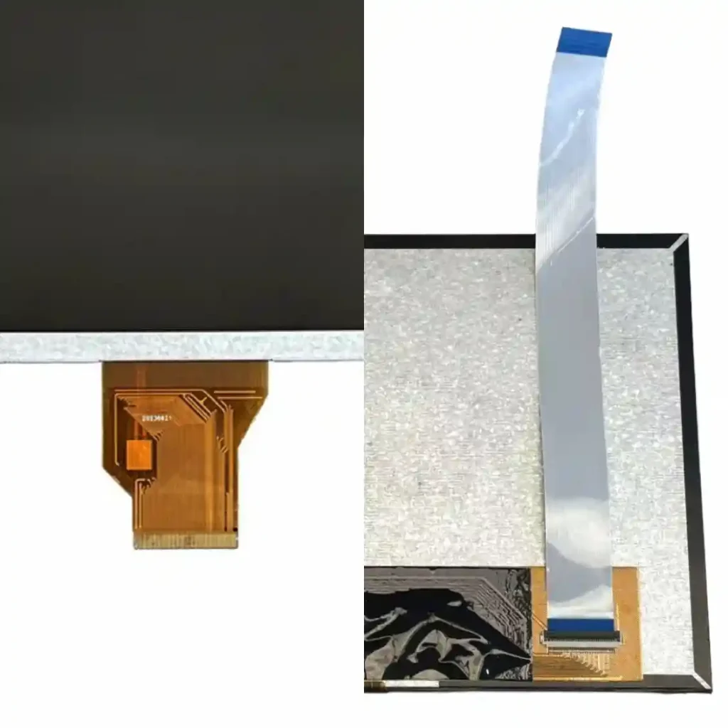
- FPC (Flexible Printed Circuit): a custom flexible circuit designed to route signals from the driver IC to the system. FPC is part of the module’s electrical design. It is not simply a wire.
- FFC (Flat Flexible Cable): a standard flat cable with parallel conductors. FFC is external and requires connectors at both ends. It cannot be customized for impedance or EMI control.
These differences lay the foundation for understanding why FPC and FFC are not interchangeable in most high-speed display applications.
FPC vs FFC Comparison Table
| Dimension | LCD FPC | FFC |
|---|---|---|
| Nature | Custom printed circuit | Standard cable |
| Role | Part of the module signal design | Connects two connectors |
| Impedance control | Built-in, engineered | Not inherent |
| EMI strategy | Designed with panel and IC | Depends on external PCB |
| Mechanical form | Bonded to module | Detachable |
| Signal complexity | High-speed and mixed signals | Low-speed, standard wiring |
Using FPC on Display Modules
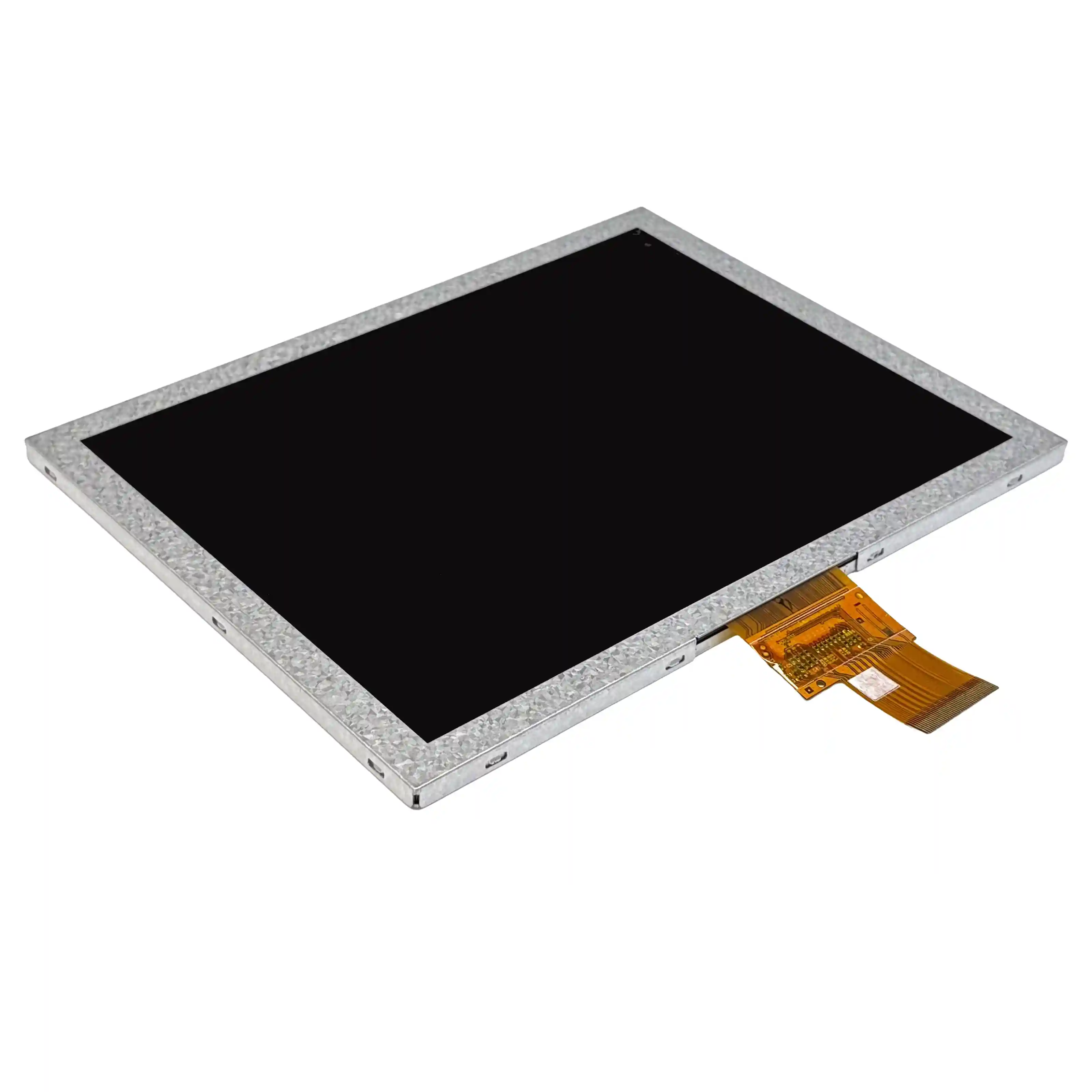
FPC is almost always necessary in TFT LCD modules, especially for small to medium sizes. The reasons include:
- Driver IC integration: Modern driver ICs are bonded directly to the glass. Signals must be routed precisely.
- Complex routing: Data lines, clocks, control lines, and touch panel signals share limited space.
- Impedance control: High-speed signals such as RGB or MIPI require precise trace width, spacing, and matched lengths.
- EMI considerations: FPC design often incorporates grounding and shielding to reduce interference.
- Bending and durability: Flexible traces must survive bending and assembly stress.
- Limited space: Small TFT modules cannot accommodate connectors without increasing bezel or module thickness.
- Mixed signal routing: Backlight, power, and touch panel signals coexist, requiring careful separation.
Conclusion: For TFT LCD and touch modules, FPC is almost always the practical solution for reliably delivering signals from the panel to the system.
How Display Interface Determines LCD FPC Design
This is the core insight of the article.
The display interface — SPI, RGB, LVDS, or MIPI — dictates internal FPC design:
- SPI interfaces: A low-speed interface with relaxed timing and signal integrity requirements, but still relies on FPC-based routing inside the module.
- RGB interfaces: Require parallel data lines, clock lines, and proper spacing to prevent crosstalk.
- LVDS / MIPI DSI: High-speed differential pairs require precise impedance, equal length routing, and shielding.
- Power and ground: Critical for VGH, VGL, AVDD, VCOM, and LED backlight circuits.
In short, the FPC is not just a cable; it is part of the interface design. The display interface enforces rules on how the FPC traces are routed, where shielding is placed, and how power lines are managed.
Key takeaway: The interface does not mandate whether the module outputs FPC or FFC externally. It mandates that the TFT FPC design meets signal integrity and EMI requirements.
Using FFC on Display Modules
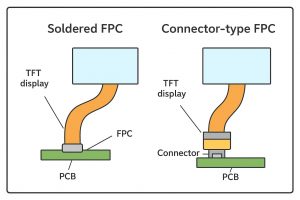
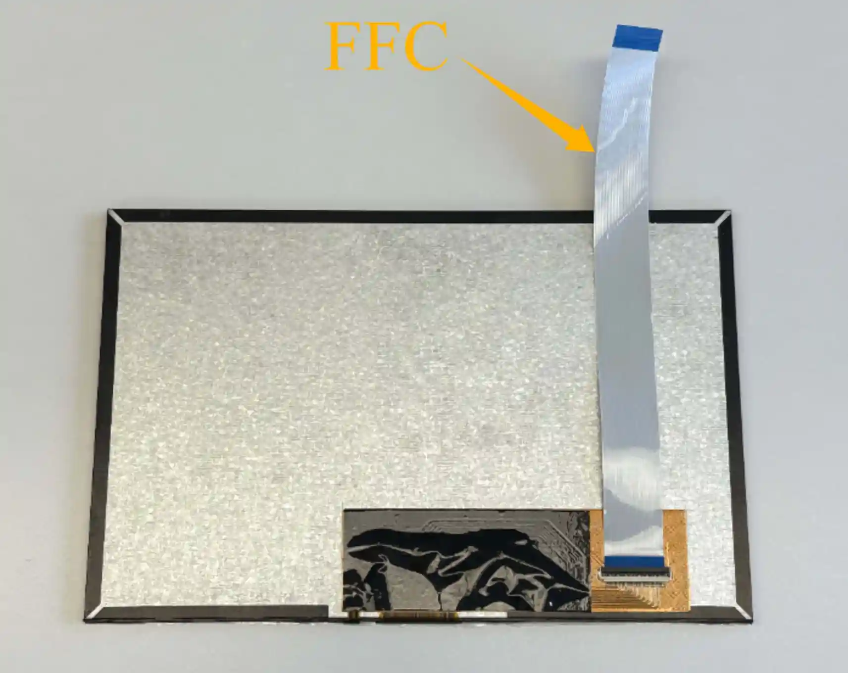
In larger modules or when modular replacement is needed, some designs adopt:
-
- Internal FPC or PCB to implement the display interface.
- An FFC connector on the module.
- External FFC cable to connect to the customer’s mainboard.
Advantages
- Modular and replaceable: Easy field maintenance.
- Standardized cable: Reduces assembly errors.
- Suitable for large modules: Space constraints are less restrictive.
Limitations
- Adds extra PCB or stiffener: Increases module thickness and cost.
- FFC cannot replace FPC: Internal routing still requires FPC for high-speed signals.
- EMI and impedance control transfer to the customer: The system designer now bears responsibility for signal quality.
Complete Comparison Table: LCD FPC vs FFC
| Dimension | LCD FPC | FFC |
|---|---|---|
| Signal control | Engineered for high-speed interface | Standard cable, no inherent control |
| Module integration | Bonded, part of the design | External, requires connector |
| Mechanical flexibility | Integrated and optimized | Detachable and modular |
| EMI / Shielding | Included in design | Needs external PCB for control |
| Suitable module size | Small to medium | Medium to large |
| Assembly complexity | Simpler for compact modules | Adds connector and FFC routing |
| Signal integrity responsibility | LCD manufacturer | Customer or system designer |
Engineer’s Decision Checklist
To choose between FPC and FFC:
- What is the display interface type (RGB, LVDS, MIPI)?
- Does the interface require impedance control and EMI management?
- Is compactness critical for the module design?
- Is modular replacement or field maintenance a priority?
- Who is responsible for signal integrity verification?
Answering these questions quickly clarifies whether direct FPC output or connector + FFC is suitable.
Conclusion: FPC vs FFC Is an Electrical Architecture Decision
The debate of FPC vs FFC is often misunderstood as a simple cable choice. In reality:
- The display interface dictates internal FPC design.
- Even if an FFC connector is used externally, internal FPC is required to maintain signal integrity.
- System designers should recognize that FFC does not replace FPC; it only provides a modular connection externally.
For engineers, the most effective approach is to start from the display interface and overall module architecture, and then decide whether FFC-based mechanical interconnects are needed. This ensures stable signal performance, proper EMI behavior, and a more predictable design and validation process in TFT LCD and touch applications.