TFT display timing determines when the panel receives valid pixels and how those pixels form lines and frames. An 800 × 480 output can still display incorrectly if its blanking intervals, pixel clock, or signal polarities do not match the panel. Start with the panel timing table, then check how the controller expects those values to be entered.
The RK050HR18-CTG example below shows how LCD timing parameters map to an 800 × 480 RGB output in Linux Device Tree.
What Happens Between the Visible Pixels?
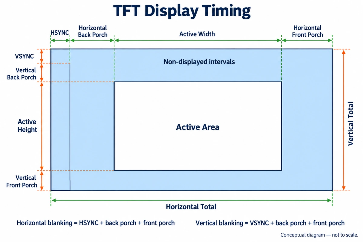
Each frame contains active video and blanking intervals. Horizontal blanking is counted in pixel-clock periods; vertical blanking is counted in lines. These intervals add to the transmission time without increasing the visible resolution. The display controller generates them separately from the active image stored in the framebuffer.
- Active area: the pixels displayed on each line and the active lines in each frame.
- Horizontal front porch (HFP): the interval after the last active pixel and before the horizontal sync pulse.
- Horizontal sync width (HSW): the duration of the horizontal synchronization pulse.
- Horizontal back porch (HBP): the interval after the sync pulse ends and before the next active line begins.
- Vertical front porch (VFP), sync width (VSW), and back porch (VBP): the corresponding frame intervals, normally counted in lines.
In conventional sync-based timing, the sequence is active video, front porch, sync pulse, back porch, then active video again. Read the waveform as well as the labels: a manufacturer’s combined blanking field may group intervals differently from your controller’s settings.
DE Mode Still Needs Blanking
Data Enable (DE) marks the interval containing valid pixel data. In DE-only operation, the receiving panel uses DE and the clock to identify the active image rather than relying on separate HSYNC and VSYNC inputs. This does not remove the inactive intervals between lines and frames.
When configuring TFT display timing in DE-only mode, you may still need to enter porch and sync widths. The controller uses these values to position the DE window and set the line and frame periods.
Do not assume that DE mode makes all porch allocations interchangeable. Check the panel’s timing diagram and the requirements of any bridge between the controller and panel.
Calculating the Pixel Clock
For progressive raster timing expressed as one pixel position per clock, use these relationships:
- Horizontal total = active width + horizontal blanking.
- Vertical total = active height + vertical blanking.
- Horizontal blanking = HFP + HSW + HBP for conventional separate-sync timing.
- Vertical blanking = VFP + VSW + VBP for conventional separate-sync timing.
- Pixel clock = horizontal total × vertical total × refresh rate.
- Line frequency = pixel clock ÷ horizontal total.
Use hertz for refresh rate; the resulting pixel clock is in hertz. Divide by 1,000,000 for megahertz. This is the raster pixel rate, not automatically the serial bit rate of the physical interface.
RK050HR18-CTG: Reading a Real Timing Table
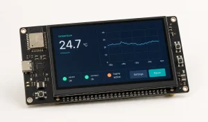
Rocktech’s RK050HR18-CTG is an 800 × 480 TFT display with a parallel 24-bit RGB interface. Its timing table lists the pixel clock, active dimensions, porches, and synchronization pulse widths. The RK050HR18-CTG uses a parallel 24-bit RGB interface. Its TFT display timing table specifies clock frequency, line and frame periods, porches, and sync widths.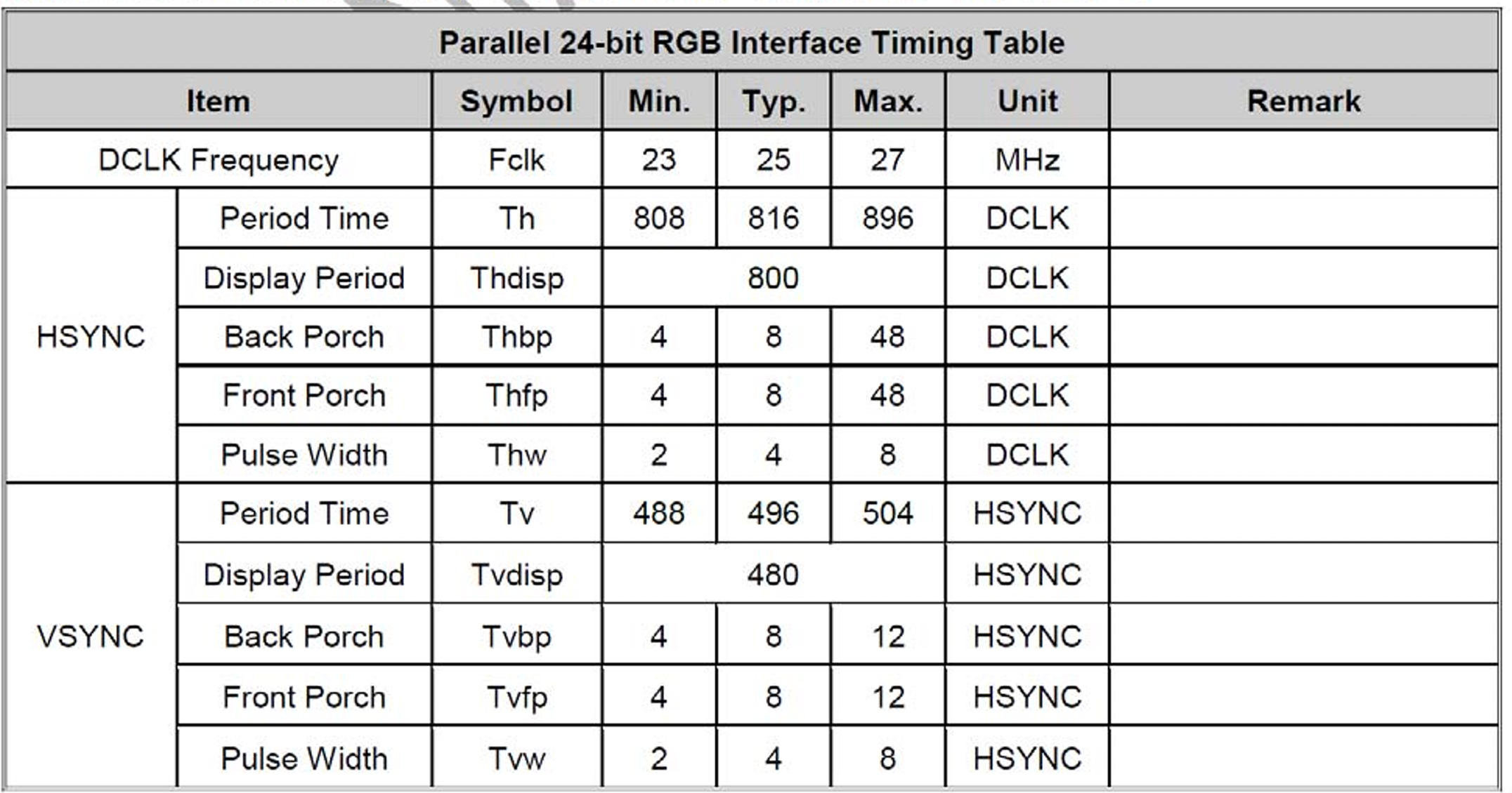
DCLK denotes pixel-clock periods. The vertical units are labeled HSYNC in the specification, meaning complete line periods. A vertical porch of eight therefore represents eight lines, not eight pixel clocks.
Device Tree Configuration Example
The following Linux Device Tree snippet uses a 25 MHz pixel clock, eight-unit front and back porches, and four-unit sync widths. The clock-frequency property is expressed in hertz, so 25000000 represents 25 MHz.
timing0: timing0 {
    clock-frequency = <25000000>;
    hactive = <800>;
    vactive = <480>;
    hback-porch = <8>;
    hfront-porch = <8>;
    vback-porch = <8>;
    vfront-porch = <8>;
    hsync-len = <4>;
    vsync-len = <4>;
    hsync-active = <1>;
    vsync-active = <1>;
    de-active = <0>;
    pixelclk-active = <1>;
};
Under standard Linux timing definitions, sync width is counted separately from both porches. The resulting TFT display timing is:
- Horizontal total = 800 + 8 + 8 + 4 = 820 pixel clocks.
- Vertical total = 480 + 8 + 8 + 4 = 500 lines.
- Refresh rate = 25,000,000 ÷ (820 × 500) ≈ 60.98 Hz.
The calculated totals of 820 clocks and 500 lines fall within the listed ranges of 808–896 and 488–504. The 25 MHz clock also falls within the specified 23–27 MHz range. The 820-clock line period and 500-line frame period are within the table’s stated ranges. The 25 MHz pixel clock is also within its 23–27 MHz range. Signal polarity and clock-edge settings need a separate check.
The table’s typical totals, 816 and 496, are not the totals produced by this code. Those printed values equal active size plus the two typical porches without separately adding the four-unit sync width. Confirm the datasheet’s interval boundaries before translating them into controller fields. For this snippet, use 820 × 500 when calculating refresh rate, rather than mixing its settings with the printed typical totals.
In the standard Linux binding, hsync-active and vsync-active set to 1 request active-high synchronization, while de-active set to 0 requests active-low data enable. A pixelclk-active value of 1 specifies driving data on the rising edge and sampling on the falling edge. The timing table alone does not confirm these choices; check their interpretation in the board’s display driver and interface path.
Turning the Table into Controller Settings
- Confirm the module version. Match the supplied panel, interface, and specification revision before borrowing a working configuration.
- Resolve the blanking split. Obtain the applicable waveform or confirmed configuration from Rocktech. Do not invent separate porch and sync values from the combined totals.
- Translate the controller fields. Some registers expect cumulative positions or counts minus one. Check whether the driver already performs that conversion.
- Verify the generated clock. Clock-divider rounding can change the actual refresh rate. Calculate using the clock the hardware produces.
- Check the electrical timing. Verify DE polarity, the sampling edge, and data setup and hold requirements for the actual interface path.
For initial TFT display timing checks, display a one-pixel border and alternating black-and-white columns. If the border is clipped, start with the active-area size and position. If the pattern is corrupted, check the clock edge, signal integrity, and any controller underrun reports.
FAQ
Can two 800×480 panels use the same timing?
Not necessarily. Resolution specifies the active image, but panels can require different total periods, clock ranges, polarities, and interface configurations. Compare both specifications before reusing LCD display timing settings. Even when a picture appears, that alone does not establish compliance with the replacement panel’s timing limits.
Does increasing the pixel clock always increase refresh rate?
Only when the horizontal and vertical totals stay unchanged does refresh rate increase in direct proportion to pixel clock. The resulting mode must still meet the panel and controller limits. A higher clock also demands adequate data delivery, so raising it is not a general cure for flicker.
What should I send Rocktech when requesting timing support?
Send Rocktech the exact module revision, host controller, interface or bridge, and complete timing node. Include the symptom, firmware version, and measured pixel clock if available. For RK050HR18-CTG, the full configuration allows the line and frame totals to be checked alongside polarity and clock-edge settings.
Start with a Complete, Consistent Mode
Correct TFT display timing begins with active dimensions, total periods, and a clock that agree mathematically. For the RK050HR18-CTG configuration above, TFT display timing works out to 820 clocks per line and 500 lines per frame. At 25 MHz, the calculated refresh rate is about 60.98 Hz. Verify the actual clock and signal settings on the target board before reusing the configuration.