Most engineers first meet Linux I2C in a simple way: two wires, one clock, one data line. But once the board is powered on and a device does not respond at 0x68, I2C quickly becomes more than a timing diagram. Many engineers first learn I2C as a two-wire communication bus. One line is SCL, the clock line. The other is SDA, the data line. A transfer starts with a START condition, ends with a STOP condition, and each byte is followed by an ACK or NACK.
These descriptions are correct, but they are not enough. If we only memorize the timing rules, I2C can still feel fragmented when we later read chip datasheets, Linux drivers, Device Tree files, or oscilloscope waveforms. The better way to understand I2C is to begin with a more basic question: why was such a bus needed in the first place?
A typical embedded board is not built around the main processor alone. Around the processor there may be many small peripheral devices: EEPROM, RTC, PMIC, temperature sensors, humidity sensors, accelerometers, touch controllers, audio codecs, GPIO expanders, and clock chips. If each of these devices required its own dedicated data lines and control signals, the processor would quickly run out of pins.
I2C was created to solve exactly this type of board-level communication problem. Its purpose is not high bandwidth. Its real value is that it allows multiple low-speed devices to share the same simple bus.
1. What Is I2C?
Why Was I2C Created?
I2C, short for Inter-Integrated Circuit, is a synchronous serial bus designed for short-distance communication between chips on the same PCB or inside the same electronic product.
It uses only two signal lines:
| Signal | Meaning | Function |
|---|---|---|
| SCL | Serial Clock | Provides the timing reference for data transfer |
| SDA | Serial Data | Carries address, data, ACK, and NACK information |
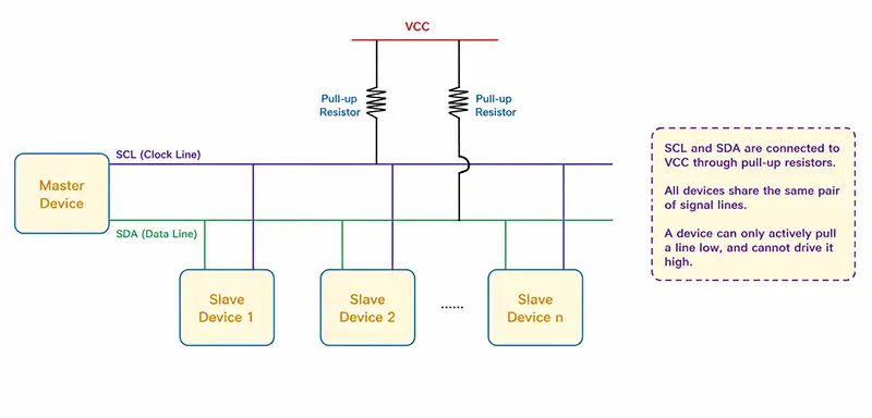
The key point is that I2C is not just a two-wire connection between two chips. It is a shared bus. One master can communicate with multiple slave devices through the same SCL and SDA lines. The master selects the target device by sending an address.
This makes I2C different from SPI. SPI commonly uses a separate chip select signal for each device. I2C instead uses an address mechanism, so the master does not need many extra GPIOs just to select peripherals.
A more accurate definition would be:
I2C is a synchronous serial bus protocol for short-distance board-level communication. It uses SCL and SDA to implement addressing, control, and data exchange between a master device and one or more slave devices on a shared bus.
Serial and Synchronous Communication
People often say that I2C is serial because it has only one data line. That explanation is not completely wrong, but it is not precise enough.
I2C is serial because data is transmitted bit by bit in time order. The bits are not sent in parallel. Each bit is placed on SDA, and SCL tells the receiver when that bit is valid and should be sampled.
I2C is also synchronous because the clock is explicitly provided on SCL. This is different from UART. In UART, both sides rely on agreed baud rate timing. In I2C, the receiver follows the clock generated by the master.
| Interface | Clock Method | Typical Use |
|---|---|---|
| UART | No shared clock, baud rate based | Point-to-point serial communication |
| SPI | Dedicated clock line | High-speed peripherals |
| I2C | Shared clock line | Low-speed board-level devices |
2. The Electrical Foundation of I2C
Why Multiple Devices Can Share the Same Two Lines
If many devices are connected to the same SCL and SDA lines, a natural question appears: why do they not fight each other electrically?
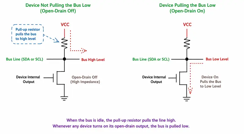
The answer is in the electrical design of I2C. I2C devices normally use open-drain or open-collector outputs. This means a device can actively pull the bus low, but it does not actively drive the bus high.
When a device wants to output a low level, it pulls the line down. When it wants to output a high level, it simply releases the line. The line then returns to high level through a pull-up resistor.
This is very different from a normal push-pull GPIO output. A push-pull output can actively drive both high and low. If two push-pull outputs are tied together and one drives high while another drives low, there will be a direct conflict. I2C avoids that situation by allowing devices only to pull the line low or release it.
Pull-Up Resistors Are Part of the Bus
Because I2C devices do not actively drive high level, both SDA and SCL require pull-up resistors connected to the bus voltage.
When no device pulls the line low, the pull-up resistor brings the line to high level. When any device pulls the line low, the bus becomes low.
| Bus State | Electrical Meaning |
|---|---|
| Low | At least one device is pulling the line down |
| High | All devices have released the line, and the pull-up resistor pulls it high |
That is why, on a normal idle I2C bus, both SCL and SDA should sit at high level.
This also explains the so-called wired-AND behavior. If any device outputs 0, the final bus level becomes 0. Only when all devices release the bus can the line become 1.
This electrical behavior is the foundation of many I2C mechanisms, including ACK, clock stretching, arbitration, and multi-master support.
3. How I2C Communication Works
Communication Flow Overview
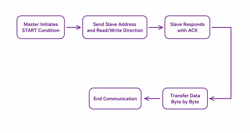
A typical I2C transaction is initiated by the master. The slave device does not start communication by itself. It waits for the master to address it.
A simplified write operation usually looks like this:
    START
    Slave Address + Write Bit
    ACK
    Register Address
    ACK
    Data
    ACK
    STOP
A typical register read operation often looks like this:
    START
    Slave Address + Write Bit
    ACK
    Register Address
    ACK
    REPEATED START
    Slave Address + Read Bit
    ACK
    Data From Slave
    NACK
    STOP
This “write first, then read” pattern confuses many beginners. The reason is simple: before reading data, the master often needs to tell the slave which internal register it wants to read. Sending the register address is a write operation on the bus, even though the final purpose is to read data.
START and STOP Conditions
When the I2C bus is idle, both SCL and SDA are high.
A START condition occurs when SDA changes from high to low while SCL remains high. This tells all devices on the bus that a new communication sequence is starting.
A STOP condition occurs when SDA changes from low to high while SCL remains high. This tells the bus that the current transaction has ended.
| Condition | SCL | SDA Transition |
|---|---|---|
| START | High | High to Low |
| STOP | High | Low to High |
During normal data transfer, SDA should not change while SCL is high. That is why START and STOP can be recognized as special control conditions.
Data Validity Rule
The most important timing rule of I2C is simple:
During data transfer, SDA must remain stable while SCL is high. SDA is allowed to change only while SCL is low.
A practical way to understand this is:
- SCL low: prepare the next bit on SDA.
- SCL high: receiver samples the current SDA value.
If SDA changed freely while SCL was high, the receiver could not reliably distinguish data from START or STOP conditions.
Address Byte and R/W Bit
The most common I2C addressing mode uses a 7-bit slave address. However, the first byte sent on the bus contains 8 bits: 7 address bits plus 1 read/write bit.
| Bits | Meaning |
|---|---|
| Bit 7 to Bit 1 | 7-bit slave address |
| Bit 0 | R/W bit |
If the R/W bit is 0, the master writes to the slave. If it is 1, the master reads from the slave.
This is where many engineers get confused when reading older datasheets. Some datasheets show addresses such as 0xA0 and 0xA1. In many cases, these are not pure 7-bit addresses. They are 8-bit address bytes after the 7-bit address has been shifted left and combined with the R/W bit.
For Linux development, it is usually important to use the 7-bit address. For example, if a datasheet lists 0xA0 for write and 0xA1 for read, the Linux I2C address is usually 0x50.
ACK and NACK Mechanism
I2C transfers data in 8-bit units. After each byte, there is a ninth clock cycle for ACK or NACK.
During the ACK bit, the receiver pulls SDA low to acknowledge that it has received the byte. If SDA remains high, that is treated as NACK.
| Response | SDA Level During ACK Clock | Meaning |
|---|---|---|
| ACK | Low | Byte accepted |
| NACK | High | No acknowledge, or transfer should end |
NACK does not always mean an error. During a multi-byte read, the master often sends ACK after each byte it wants to continue receiving. After the final byte, the master sends NACK to tell the slave that the read is finished.
So ACK and NACK are not only success or failure flags. They are also flow control signals at byte boundaries.
4. Advanced I2C Features
Clock Stretching
Although the master normally provides the clock, some slaves may need more time to prepare data. In that case, a slave can hold SCL low. This is called clock stretching.
The master may try to release SCL high, but because the slave is still pulling it low, the bus remains low. The transfer continues only after the slave releases SCL.
This works because SCL is also open-drain. Any device can hold the line low.
Not every controller or driver handles clock stretching equally well. In real projects, this can become a compatibility issue, especially with slow sensors or software-emulated I2C implementations.
Multi-Master Arbitration
I2C theoretically supports multiple masters on the same bus. In most embedded Linux systems, single-master operation is more common, but understanding arbitration helps explain the bus design.
If two masters transmit at the same time, each master monitors the actual bus level while sending.
If a master releases SDA to send a high level but reads back a low level, it knows another master is pulling the line low. Since low level wins on an open-drain bus, this master loses arbitration and must stop transmitting.
This arbitration mechanism does not require extra wires. It depends entirely on the wired-AND behavior of the I2C bus.
I2C vs SMBus
In Linux drivers, engineers often see both i2c_* APIs and i2c_smbus_* APIs. This sometimes creates the impression that I2C and SMBus are the same thing.
They are related, but not identical. SMBus is built on top of I2C-like electrical and signaling concepts, but it defines stricter rules for timing, voltage levels, timeout behavior, and transaction formats.
| Item | I2C | SMBus |
|---|---|---|
| Purpose | General chip-to-chip communication | System management communication |
| Timing | More flexible | More constrained |
| Timeout | Not always required | Defined behavior |
| Linux APIs | i2c_transfer, i2c_master_send | i2c_smbus_read/write functions |
Many I2C devices are compatible with SMBus-style register access, but engineers should not assume the two standards are completely interchangeable.
5. Linux I2C Subsystem Overview
Once we move from waveform analysis to Linux driver development, the focus changes. In Linux, we no longer manually generate START, STOP, and ACK signals in a normal device driver. Instead, we work with the I2C subsystem.
Several key objects define the Linux I2C architecture:
| Object | Meaning |
|---|---|
| i2c_adapter | Represents an I2C bus or controller |
| i2c_client | Represents one slave device on the bus |
| i2c_driver | Represents the driver for a class of I2C devices |
| i2c_algorithm | Defines how the adapter performs transfers |
6. Key Linux I2C Objects
i2c_adapter: The Bus Instance
An i2c_adapter represents one I2C controller in the kernel. On a Rockchip or NXP board, each enabled hardware I2C controller usually appears as one adapter in Linux. That is why changing the bus number in Device Tree or board configuration can directly affect where the device appears.
For example, if an SoC has I2C0, I2C1, and I2C2, Linux may register three different i2c_adapter instances.
The adapter does not describe a specific sensor or EEPROM. It describes the bus itself and provides a way for devices on that bus to communicate.
i2c_client: A Device on the Bus
An i2c_client represents a specific slave device attached to an I2C adapter.
Important information usually includes:
- The slave address
- The adapter it belongs to
- The device structure
- Device Tree or board information
For example, if an MPU6050 sensor is connected to I2C1 at address 0x68, Linux will create an i2c_client representing that physical device instance.
i2c_driver: The Device Driver
An i2c_driver is the driver code for a type of I2C device. It is not a single hardware instance.
It usually contains:
- probe function
- remove function
- match table
- power management callbacks
When Linux finds that an i2c_client matches an i2c_driver, it calls the driver’s probe function. The driver can then initialize the hardware and register any required input, sensor, RTC, regulator, or other subsystem interfaces.
i2c_algorithm: How Transfers Are Done
The i2c_algorithm object is usually provided by the I2C controller driver. It defines how actual transfers are executed on that adapter.
The adapter tells Linux that a bus exists. The algorithm tells Linux how transfers should be performed on that bus.
This separation allows the same device driver to work on different SoCs. A GT911 touchscreen driver, for example, does not need to know the internal register layout of the Rockchip or NXP I2C controller. It simply sends I2C messages through the kernel I2C core.
7. Device Discovery and Driver Matching
In a typical embedded Linux system, the flow looks like this:
    I2C controller driver registers i2c_adapter
    Device Tree describes slave devices under that bus
    Kernel creates i2c_client instances
    i2c_driver is registered
    Kernel matches client and driver
    Driver probe function is called
The important relationship is:
- i2c_adapter represents the bus
- i2c_client represents the device
- i2c_driver manages the device
- i2c_algorithm performs the low-level transfer
Once this model is clear, Linux I2C driver code becomes much easier to read.
8. Linux I2C APIs and Debugging
Common I2C APIs
The most general transfer API is:
    int i2c_transfer(struct i2c_adapter *adap,
                     struct i2c_msg *msgs,
                     int num);
It sends one or more I2C messages through a specified adapter.
Simple master send and receive helpers include:
    int i2c_master_send(const struct i2c_client *client,
                        const char *buf,
                        int count);

    int i2c_master_recv(const struct i2c_client *client,
                        char *buf,
                        int count);
For register-style devices, SMBus helper functions are commonly used:
    s32 i2c_smbus_read_byte_data(const struct i2c_client *client,
                                 u8 command);

    s32 i2c_smbus_write_byte_data(const struct i2c_client *client,
                                  u8 command,
                                  u8 value);
Other common helpers include:
    i2c_smbus_read_word_data()
    i2c_smbus_write_word_data()
    i2c_smbus_read_i2c_block_data()
    i2c_smbus_write_i2c_block_data()
These APIs cover many common sensors, PMICs, RTCs, EEPROMs, and touch controllers.
Using i2c-tools
During board bring-up, i2c-tools are very useful.
Common commands include:
    i2cdetect -y 1
    i2cget -y 1 0x68 0x00
    i2cset -y 1 0x68 0x00 0x12
These tools help verify whether the bus is alive, whether a device responds, and whether registers can be accessed.
However, they should be used carefully. Writing incorrect values to PMICs, touch controllers, or clock chips can cause unexpected behavior.
Conclusion
I2C looks simple until the first device refuses to ACK. After that, the electrical layer, timing rules, addressing format, and Linux driver model all start to matter. Its two-wire structure, open-drain electrical design, pull-up resistors, address mechanism, ACK/NACK behavior, repeated START, clock stretching, and Linux driver model all connect into one complete system.
For embedded engineers, understanding I2C only at the timing-diagram level is not enough. It is also necessary to understand why the bus is designed this way, how electrical sharing works, how Linux abstracts the bus, and how device drivers communicate through the I2C core.
Once these pieces are connected, I2C becomes much easier to debug in real projects. Whether working with sensors, PMICs, RTCs, EEPROMs, touch controllers, or display-related chips, a clear understanding of I2C remains one of the most useful skills in embedded Linux development.