Introduction
G+G (Glass + Glass) is a common PCAP touch panel structure that uses a cover glass as the outer protective layer and a second glass substrate to carry the touch-sensing electrodes. Because the sensing technology is based on projected capacitive touch, a G+G touch panel can provide a rigid and durable touch surface while maintaining the benefits of PCAP sensing.
G+G is not the only way to construct a PCAP touch panel. Depending on requirements such as thickness, weight, rigidity, optical performance, durability, and application environment, manufacturers may use different sensor configurations. Understanding the PCAP touch panel structure is therefore important when selecting a touch solution for a specific device.
What Is G+G Touch?
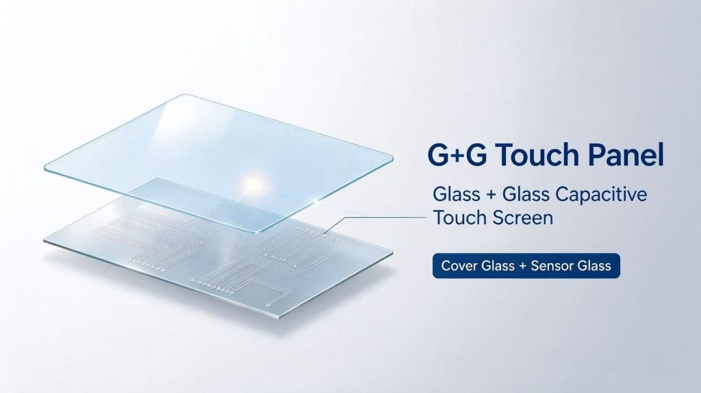
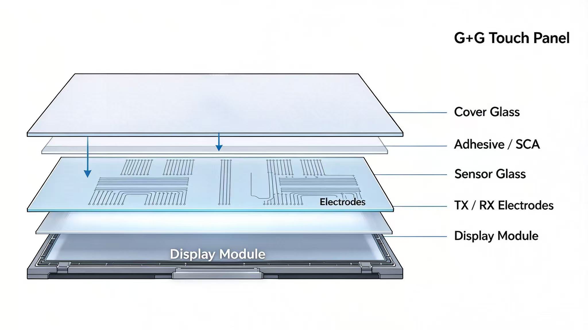
The G+G touch panel structure consists of a cover glass, a bonding layer (SCA), and a glass-based touch sensor, which are assembled above the display module. Although both the cover and sensor substrates are made of glass, they serve different purposes within the touch system.
- Cover glass: The outer layer provides the touch surface and protects the underlying sensor and display. Depending on the application, it can be customized with AG, AF, or AR treatment, black borders, logos, or strengthened thicker glass.
- Sensor glass: Located beneath the cover glass, this substrate carries the conductive touch-sensing ITO electrodes. Together with the touch controller, these electrodes detect changes in capacitance caused by a finger or other conductive object, and different touch controller has different ITO patterns.
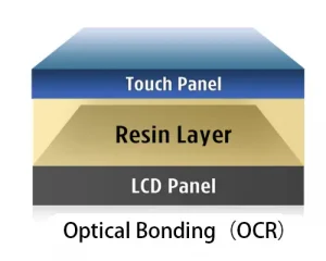
- Adhesive / SCA: The cover glass and sensor are joined using an adhesive or SCA. Optical bonding can improve visual performance by reducing reflections and the air gap between layers.
- Display module: The LCD or OLED module is located below the touch panel and provides the image displayed to the user.
A simplified G+G touch panel structure can be illustrated as follows:
How Does a G+G Touch Panel Work?
A G+G touch panel combines a glass cover, a glass-based touch sensor, and a touch controller to detect touch input and convert it into coordinates that the host device can understand. The basic process starts when a finger approaches the touch surface, and ends when the controller sends the detected touch position to the system.
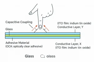
The cover glass forms the outer touch surface and it also protects the sensor underneath. Below the cover glass, the touch sensor glass contains conductive TX and RX electrodes. In a typical projected capacitive (PCAP) design, these electrodes form a sensing grid. When a finger approaches the surface, it changes the local electrical field and capacitance at the corresponding sensing area.
The touch controller continuously monitors these changes. It processes the signals from the sensor electrodes, determines the position of the touch, and sends the resulting touch coordinates to the host system through an interface such as I2C or USB. The host system can then use these coordinates to control the user interface displayed on the LCD or OLED.
In simple terms, the process can be summarized as:
Finger touches → capacitance changes → sensor electrodes detect the change → touch controller calculates the coordinates → host system receives the touch position.
For the conection between the cover glass and touch sensor glass, they can be bonded using an adhesive SCA or OCA (Optically Clear Adhesive). These optical bonding adhesive can reduce the reflections caused by an air gap and improve display readability. But the bonding method also needs to be considered together with factors such as panel thickness, optical clarity, bubbles, and the mechanical requirements of the application.
What Are the Different Touch Panel Structures/Touchscreen Technologies?
Different touch panel structures are designed to balance factors such as thickness, weight, rigidity, optical performance, touch sensitivity, durability, and manufacturing complexity. G+G and G+F are external touch-panel structures, while OGS, On-Cell, and In-Cell integrate the touch-sensing function more closely with the display.
| Structure | Basic configuration | Main characteristics | Typical considerations |
|---|---|---|---|
| G+G | Glass cover + glass sensor | Rigid, robust, suitable for larger or demanding touch surfaces | Thickness, weight, cost |
| G+F/G+F+F | Glass cover + film sensor/+film sensor*2 | Can be thinner and lighter, with greater sensor flexibility | Mechanical rigidity and application requirements |
| OGS | One glass substrate integrates the cover and touch sensor | Fewer layers and potentially thinner optical stack | Glass processing, sensor integration, repairability |
| On-Cell | Touch sensor integrated on or within the display cell, typically on the upper side | Reduced thickness and air gap compared with separate touch panels | Display compatibility and integration requirements |
| In-Cell | Touch-sensing function integrated inside the display cell | Highly integrated and potentially very thin | More complex display manufacturing and limited customization |
How Do You Choose the Right Structure?
There is no single touch panel structure that is suitable for every application. The choice depends on the priorities of the device:
- Need a rigid and robust touch surface? G+G can be considered.
- Need lower weight or a thinner structure? G+F may be suitable depending on the design.
- Need to reduce the number of glass layers? OGS may be an option.
- Need a highly integrated display and touch solution? On-Cell or In-Cell may be considered.
- Need extensive customization of the cover glass, sensor, or touch panel? A separate PCAP structure such as G+G or G+F may provide more design flexibility.
The structure should not be selected based on the touch technology alone. Cover glass thickness, sensor design, display type, bonding method, optical requirements, mechanical durability, operating environment, production volume, and customization requirements should all be evaluated together.
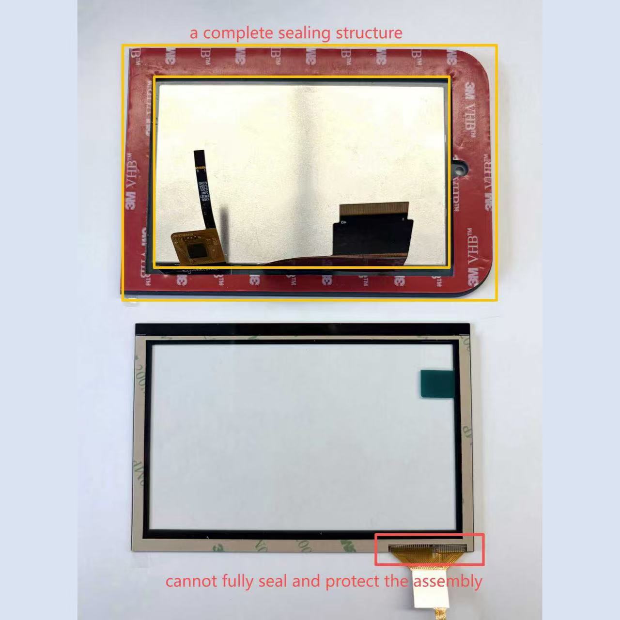
Real-World Example: Selecting a Touch Structure for a Waterproof Application
In one industrial touch display project, the customer required the touchscreen to remain reliable in a water-exposed environment. During the structural evaluation, waterproof performance was considered together with the bonding and sealing design rather than just looking at the touch structure alone.
A G+F+F configuration was selected for the project because its layer and bonding configuration could be designed to fit the required adhesive solution to achieve the IP65 sealing. As shown in the comparison above, different touch structures may use different adhesive arrangements, like the L-shaped or o one-piece VHB, and these differences can directly affect the sealing performance of the finished touch panel.
This example shows why choosing a touch panel structure for a waterproof application requires more than simply comparing G+G, G+F, or G+F+F. The sensor structure, adhesive type, bonding coverage, edge sealing, cover glass, and integration with the housing all need to be considered as part of the overall waterproof design.
Key takeaway: A G+F+F structure does not automatically make a touchscreen waterproof. Waterproof performance depends on the complete touch panel construction, including the bonding and sealing solution.