What Is Display Screen Structure?
A display screen is more than the panel shown on the front of a device. Inside, there are several components working together to produce the image. Depending on the application, a touch panel may also be added so the users can interact with the device directly through the screen.
To form the display screen structure depends on how these components are arranged and assembled to make a complete display. A typical TFT LCD module includes the LCD panel, polarizers, backlight unit, driver IC, FPC and mechanical frame. The actual structure can vary with the display size, performance requirements and end application.
TFT LCD modules are widely used in industrial and commercial equipment because they provide stable image performance and can be customized for different requirements, including brightness, operating temperature and mechanical design.
For applications that require touch operation, a PCAP touch screen can be integrated with the LCD module. This is how they work: the LCD handles the visual content, while the touch panel detects the user’s touch and sends the corresponding input to the device.
LCD Module Structure: What Is Inside an LCD Module?
TFT LCD Panel
The TFT LCD panel is where the image is formed. And its core is the LCD cell, which contains the layers responsible for controlling light and producing individual pixels.
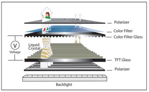
A typical LCD cell is made up of a TFT array substrate, liquid crystal layer, and color filter substrate. The TFT array controls each pixel electrically, while the liquid crystal layer controls how much light can pass through. The color filter then adds the red, green, and blue sub-pixels that make up the final color image.
There are also two polarizers inside located in the each side of the LCD cell. They control the polarization of the light passing through the cell and work together with the liquid crystal layer to form the image.
A simplified structure is:
Front Polarizer → Color Filter Substrate → Liquid Crystal Layer → TFT Array Substrate → Rear Polarizer
The main layers can be understood as follows:
- TFT Array – Controls the electrical state of individual pixels and determines how each pixel displays.
- Liquid Crystal Layer – Changes the orientation of the liquid crystal molecules when an electric field is applied, controlling light transmission.
- Color Filter (CF) – Provides the red, green, and blue sub-pixels used to create full-color images.
- Polarizers – Control the direction of polarized light passing through the LCD cell, allowing the liquid crystal layer to control the final image.
Different LCD technologies, including IPS, TN, and VA, use different liquid crystal arrangements and driving methods. For example, IPS displays are commonly chosen when wide viewing angles and consistent image quality are important, making them popular in many industrial and commercial applications.
Backlight Unit (BLU)
Because TFT LCD panels do not generate light by themselves, they require a backlight unit to illuminate the display.
A simplified edge-lit backlight structure is: LED → LGP → Reflector / Diffuser / Prism Film → LCD Panel
For most small and medium size TFT LCD modules, we usually apply an LED-based backlight for them. A typical edge-lit backlight consists of several optical components, each serving a specific function:
- LED Light Source – Provides the light source for the display.
- Light Guide Plate (LGP) – Distributes light from the LEDs across the display area and helps achieve uniform illumination.
- Reflector – Reflects light back toward the LCD panel to improve light utilization.
- Diffuser – Disperses the light and helps reduce bright spots and uneven illumination.
- Prism Film – Redirects light toward the viewing direction and helps improve the perceived brightness of the display.
The design of the backlight has a direct impact on important display specifications such as brightness, uniformity, power consumption, and operating lifetime. For applications exposed to strong ambient light, the backlight may be designed for higher brightness levels, such as 800, 1000, or even 1300-1500 nits, depending on the application requirements.
It is also worth noting that backlight performance can vary slightly between production batches causing LCD Color Problem. Factors such as the nature of the backlight, optical materials used in the LED, LGP, diffuser and other optical components, electrical calibration and manufacturing tolerances can all have impacts on the final optical performance.
In the TFT LCD industry, small variations within a reasonable range are generally considered normal and do not necessarily indicate a quality issue. However, if the difference is beyond the expected range, the backlight design and related parameters can usually be adjusted to bring the performance back to the required level.
Driver IC and FPC
In addition to the optical components, an LCD module contains electronic components that allow it to communicate with the host system. This the brain of TFT-LCD and it controls the electrical signals required to operate the LCD panel, while the FPC (Flexible Printed Circuit) provides the electrical connection between the display module and the customer’s main board.
Depending on the LCD design, common display interfaces include: LVDS/MIPI DSI/RGB/eDP/SPI
The interface, pin definition, voltage, and timing parameters need to match the customer’s mainboard and system requirements.
Frame and Mechanical Components
The LCD and backlight are typically assembled into a mechanical frame or bezel. The frame helps maintain the structural integrity of the module and protects internal components during assembly and use.
Depending on the application, the mechanical design may also include:
- Mounting holes
- Brackets
- Metal frames
- Plastic frames
- Customized bezels
- FPC routing and connector positioning
In most cases, TFT LCD suppliers provide the standard metal frame and the components that come with the display module. Mounting holes, brackets and other mechanical parts are usually customized according to the customer’s housing and installation requirements.
The display screen structure is not determined only by the optical layers. Mechanical dimensions and electrical interfaces are equally important when integrating a display into a finished product.
What Is a PCAP Touch Screen?
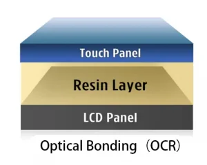
A touch panel is an input component that allows users to interact with a device by touching the display. When integrated with an LCD module, it creates a complete touch display solution: the LCD provides the image, while the PCAP touch screen provides the touch interface.
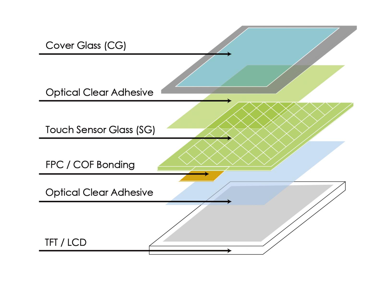
PCAP, or Projected Capacitive Touch, is one of the most widely used touch technologies for modern displays. It detects changes in the electrical field when a finger touches the screen. A typical PCAP touch panel consists of a cover glass, touch sensor, ITO electrodes, touch IC and FPC.
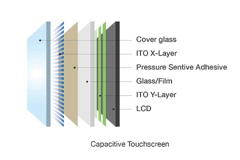
The cover glass is the outer protective layer of the touch panel. It protects the sensor from scratches, impact and daily wear, while its thickness, shape, surface treatment and printed areas can be customized according to the application.
Behind the cover glass is the touch sensor, which contains patterned conductive electrodes. ITO (Indium Tin Oxide) is commonly used to form these transparent electrodes. The ITO patterns create the sensing grid that detects changes in capacitance when a finger approaches or touches the screen.
The touch IC processes the signals from the sensor and determines the touch position, while the FPC connects the touch panel to the main control board.
A simplified PCAP touch panel structure can be shown as: Cover Glass → Touch Sensor → Touch IC → FPC
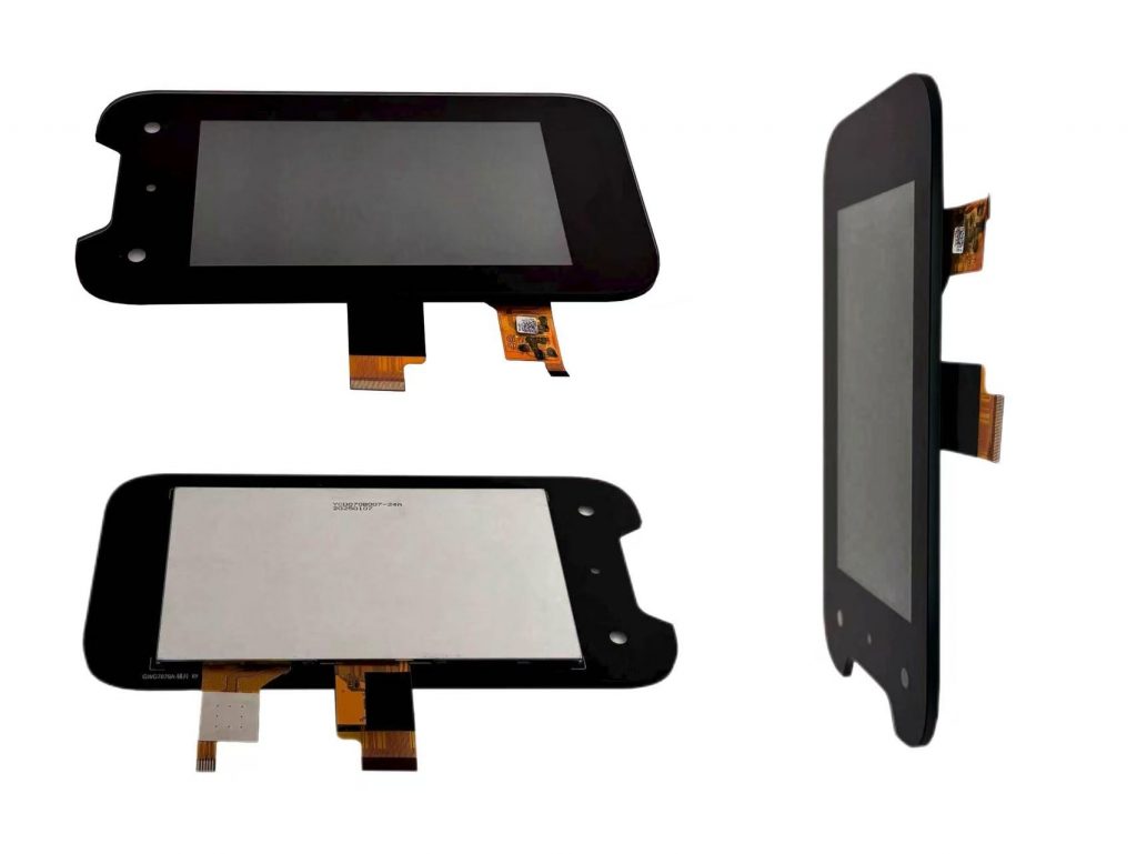
Together with the TFT LCD module, these components form the basic structure of a modern touch display.