
What Makes a TFT LCD Sunlight Readable

Sunlight readable is a performance claim rather than a product category. A display qualifies when its image keeps usable contrast under strong ambient light, which is why the same panel can be sold as a daylight-readable display by one supplier and as an indoor module by another.
A conventional industrial LCD panel emits 250–500 nits and is designed for indoor light of a few hundred lux. Direct sun reaches roughly 100,000 lux. A single air-to-glass interface at near-normal incidence reflects about 4% of the light striking it — Fresnel reflectance for a glass surface with an index near 1.52 — so an unbonded stack with two such interfaces returns on the order of 8% of the ambient light to the viewer once transmission through the first interface is counted — an estimate that ignores multiple reflections and absorption in the glass. That reflection is largely specular, so the front surface does not so much brighten evenly as mirror what is above the display: a daytime sky carries a luminance far above the panel’s own white output, and 8% of it easily exceeds it. Converting lux to cd/m² through a reflectance term only works for a diffuse surface, where L = E·ρ/π — the front glass of a glossy module is not one. The practical consequence is the same either way: the reflected light competes with a white state of a few hundred nits, and that is what flattens the image.
Emitted light versus reflected light
The measure that decides whether a screen survives outdoors is ambient contrast ratio (ACR), the white and black luminance compared after reflected light is added to both:
ACR = (LW + LR) / (LB + LR)
LW is white-state luminance, LB is black-state luminance and LR is reflected ambient luminance. Because LR sits in both terms, extra backlight raises the numerator and the denominator at once, so each additional nit buys less contrast as ambient light rises. Where that crossover falls depends on the site’s illuminance, the reflectance of the finished stack and the black level, not on a fixed nits figure — which is why once reflected light dominates, reflection control may deliver more benefit than adding backlight brightness, without the extra power and heat.
Four factors that decide the outcome
Panel luminance sets the available light. Reflection control — optical bonding plus surface treatment — decides how much of it reaches the eye. Polarizer orientation decides whether the image is visible through polarized sunglasses, a factor routinely overlooked in outdoor handheld and marine designs. Thermal design decides whether the other three still hold once the backlight has reached thermal equilibrium inside a sealed enclosure. A module has to be assessed as a finished assembly, not as a single specification.
How Many Nits Does a Sunlight Readable TFT LCD Need?
There is no universal figure, because the requirement depends on mounting, ambient light and what sits between the panel and the viewer. The bands below are starting points for a bonded stack with surface treatment, not fixed requirements.
| Condition | Typical brightness | What else to consider |
|---|---|---|
| Bright indoor, near a window | 500–800 nits | Front-surface reflection control |
| Shade, canopy, indirect sun | 800–1,000 nits | Optical bonding |
| Direct sun, intermittent exposure | 1,000–1,500 nits | Bonding plus AR or AG treatment |
| Continuous direct sun, high-glare site | 1,500–2,500+ nits | Reflection control and thermal management |
Read these as indicative ranges. The actual target follows from measured reflectance, viewing angle, content density and the enclosure, and a 1,000-nit bonded unit can outperform a 1,500-nit unbonded one for exactly that reason.
Why a 1,000-nit bonded module can beat a 1,500-nit air-gap module
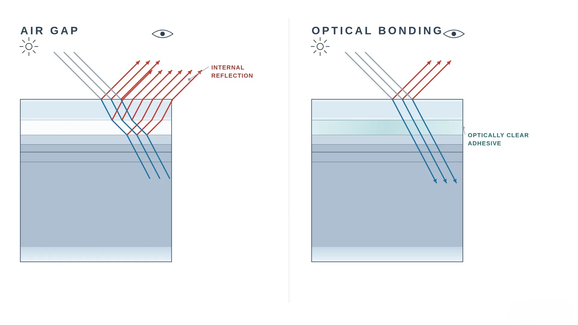
Consider two modules in one enclosure. The brighter one keeps its air gap; the dimmer one is bonded behind low-reflectance glass. Take reflected luminance measured at the viewing position under the same conditions as an input rather than deriving it: if the unbonded stack returns about 300 cd/m² at the viewing position and the bonded stack about 40 cd/m² under the same conditions, then against a 1,000-nit panel with a 5-nit black level the ambient contrast ratio moves from roughly 4:1 to roughly 23:1. Bonding removes reflections instead of out-shouting them: the brighter module’s extra nits are real, but under high ambient light much of them never reach the eye. Substitute your own measured values and the direction stays the same; the magnitude will not. Both builds sit in our high brightness module range if you want to compare them line by line.
Optical Bonding: Improving Contrast by Reducing Internal Reflections
What the air gap costs
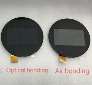
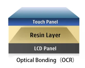
An unbonded stack has two air-to-glass interfaces, each returning about 4% of incident light at near-normal incidence — roughly 8% of ambient light coming straight back at the viewer. How many interfaces a real assembly actually has — cover glass, touch sensor, front polarizer — is set by its construction, and some builds carry more than two, so treat the figure as a two-interface estimate. That is enough to produce visible ghosting at shallow angles, and the gap itself becomes a cavity where moisture condenses after enough day–night cycles. Bonding with an index-matched adhesive (refractive index 1.47–1.52) replaces both air-to-glass interfaces with interfaces that carry almost no index step, so the reflection responsible for the ghost largely disappears, and the cavity goes with it. Because the light it removes sits in both terms of the ACR, the gain reads to the eye like extra backlight at no extra power. How large that gain is depends on cover-glass thickness, adhesive index, surface treatment and viewing angle, so it has to be confirmed by measurement on the assembled unit rather than predicted from a rule of thumb.
OCA or LOCA?
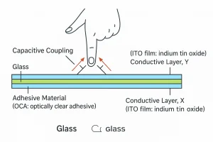
Dry-film OCA suits thin, flat stacks with a controlled bond line and is the lower-risk route for volume production. Liquid LOCA covers larger formats, thicker cover glass and stepped or curved surfaces, but needs tight control over dispense volume and cure dose to avoid haze, bubbles and later delamination. Bonding specifications are typically written around values of this order: refractive index 1.47–1.52, transmittance at or above 98% near 550 nm measured under the agreed test conditions, haze under 0.5%, yellowness shift held to a few units after 1,000 hours of UV ageing, and transmittance loss under 1% after 500 hours at 85°C/85% RH. Treat them as the kind of criteria to put on the drawing rather than as a vendor promise, and confirm them against the supplier’s own acceptance data for the process and format you are buying.
AR versus AG: Two Different Glare Problems
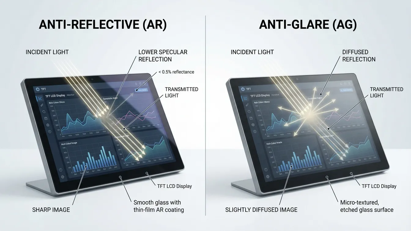
Anti-reflective and anti-glare treatments are often quoted as if interchangeable. They remove different failures.
AR coating
AR uses thin-film interference to cancel front-surface reflection. Research has also demonstrated how anti-reflective coatings improve ambient contrast while reducing the luminance required for a comparable viewing experience. Depending on the coating design and the measurement conditions, a well-matched stack can bring front-surface reflectance down to roughly 0.2–0.5% at the specified wavelength and angle; quote it as single-surface or as assembly reflectance, and always with the geometry it was measured at. It keeps the image sharp, which makes it the choice for dense text, fine trend lines and diagnostic content. The trade-offs are cost that scales with layer count and substrate size, and sensitivity to aggressive cleaning chemistry.
AG treatment
AG micro-textures the surface so a specular hotspot scatters into a broad haze instead of a mirror image of the sun. It gives up part of its specular transmission to that diffusion — how much depends on the haze level and the process — and softens detail slightly, which shows up as sparkle on high-PPI panels. AG is therefore specified by haze together with image clarity and sparkle, not by a single gloss figure: gloss depends on the measurement angle, and a finish that reads well on a test bench can still sparkle once fine text is displayed at high pixel density. Choose the cover glass against the actual content rather than against a catalogue number.
Why most outdoor stacks combine both
A common arrangement puts AG on the cover glass to break the moving hotspot and AR on the front surface to cut the residual reflection — the two are sometimes combined in a single coating — with further AR at internal interfaces only where the stack allows it. The exact build belongs to the optical design rather than to a default. Specifying one treatment and expecting it to cover the other’s failure is a common mistake in outdoor RFQs, and a 2,000-nit panel will not fix a reflection problem that only a coating or a change in installation geometry can solve.
Polarizer Orientation and Polarized Sunglasses
Why an LCD goes dark behind sunglasses
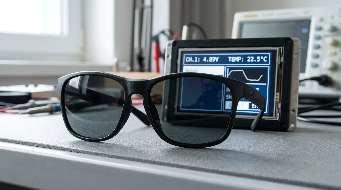
A TFT LCD carries two polarizers on opposite sides of the liquid-crystal cell, and the light leaving the panel is linearly polarized along the front polarizer’s transmission axis. This is a known design consideration for outdoor LCD applications using polarized sunglasses. Polarized sunglasses transmit only one axis as well, so the two filters sit in series. When the axes are aligned the screen looks normal. The drop follows Malus’s law: transmitted intensity scales with cos²θ, so an ideal pair of axes at 45° passes about half the light and at 90° passes effectively none. A real LCD is less clean-cut than the ideal case, because ambient reflection, viewing angle and grey-level behaviour all modify the result, but the pattern holds. The polarizer angle is a panel-level specification rather than a default, and datasheets often omit it — ask for it explicitly. What matters in the field is the relative angle between the front polarizer and the user’s sunglasses, and a mounting direction that lands near 45° of mismatch gives away about half the luminance before the backlight is even considered.
How to test and specify compatibility
Rotate the finished unit in 45° steps while looking through a representative pair of sunglasses, and record luminance at each angle with a meter rather than by eye. Set the acceptable attenuation for the intended viewing position before you test — it is a project acceptance criterion, not an industry threshold — and treat any angle that misses it as worth fixing before tooling. The fix is either a different polarizer angle at the panel, a rotated mounting orientation, or a re-laid-out front polarizer — and no single orientation covers every pair of sunglasses on the market.
The Real Cost of a High Brightness TFT Display
Power, heat and derating
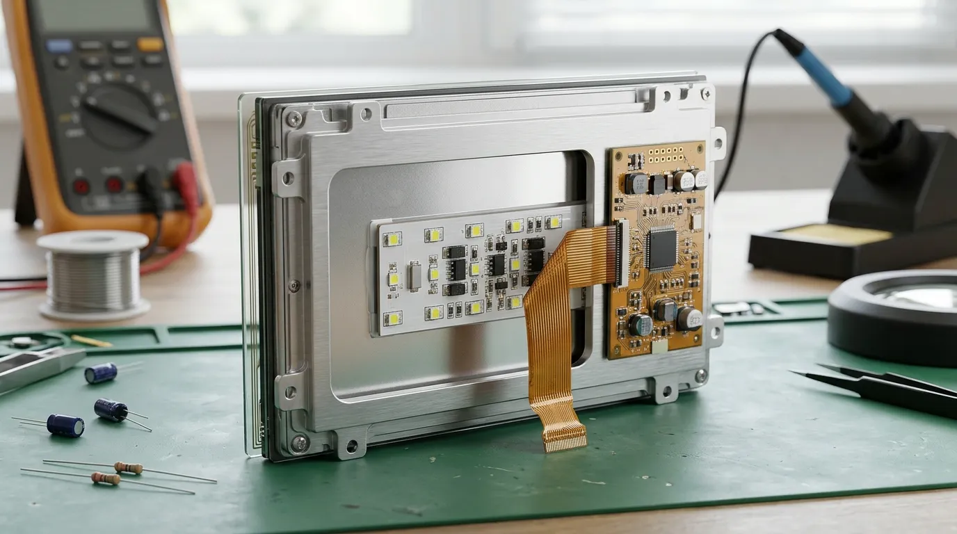
Brightness is bought with current, and current becomes heat inside a sealed enclosure. A module that measures 1,500 nits on the bench may deliver materially less once the backlight reaches thermal equilibrium at the enclosure’s working temperature. The clearing point is an intrinsic property of the liquid-crystal mixture and sits well above normal operating temperatures; what constrains a sealed design in practice is the module’s rated operating temperature together with the polarizer and backlight limits, which is why high-temperature panels are specified for outdoor builds. Running past that rating is not automatically destructive, but it can cost contrast while the unit is hot and, depending on the materials and the failure mechanism, leave a permanent loss behind.
What belongs in the RFQ
When requesting a sunlight readable TFT LCD, start with the application rather than the number: where the display will be installed, the expected ambient light, target brightness and operating temperature, plus whether it needs AR or AG treatment, optical bonding, or a polarizer that suits polarized sunglasses. If you are unsure which of those apply, say so — working that out is part of what a supplier should do for you. Optical bonding is worth evaluating in the first round because it reduces the reflection the nits figure is competing with; with reflection under control, a lower brightness target can reach the same ambient contrast. Choosing on brightness alone rarely delivers outdoor readability.
Conclusion
A sunlight readable TFT LCD needs more than a high-brightness panel. Reflection control, polarizer orientation and thermal design all affect the final result, and the right specification depends on the actual application and operating environment. Define those conditions first, then evaluate the complete assembly under representative lighting and temperature conditions.
FAQ
Is 1,000 nits enough for direct sunlight?
It depends on the reflectance of the finished stack, the bonding, the ambient illuminance and the viewing position. A 1,000-nit bonded module is sufficient for many intermittent-exposure outdoor applications, but the figure is neither a universal requirement nor a guarantee: a poorly bonded 1,500-nit unit can read worse. Confirm the result on the assembled unit at the site’s light level.
Why does a 1,000-nit screen still look grey outside?
Reflected ambient light lifts the black level as well as the white, so ambient contrast ratio collapses before luminance does. Reducing reflections within the optical stack can improve outdoor contrast, while increasing brightness alone may not solve the problem.
Why does my LCD look dark through polarized sunglasses?
An LCD emits linearly polarized light and sunglasses transmit only one polarization axis. When the two are close to perpendicular the screen dims sharply or goes almost black, so the polarizer orientation has to be checked against the mounting direction.
Does higher brightness shorten backlight life?
Higher drive current raises LED junction temperature, which accelerates lumen depreciation. A high brightness module holds its figure only when the thermal path was designed for the worst-case enclosure temperature.
Next Step
If the specification is still open, send the enclosure temperature, display size, cover-glass construction, viewing distance and the mounting direction — the last one decides polarizer orientation. Rocktech Displays builds industrial modules from 0.96″ to 15.6″ with IPS panels and wide-temperature options, supplies high brightness backlights, and handles optical bonding, AG or AR coating and touch integration in-house, so the optical stack and the panel come from one line instead of three suppliers — contact us to discuss a sunlight readable TFT LCD solution.