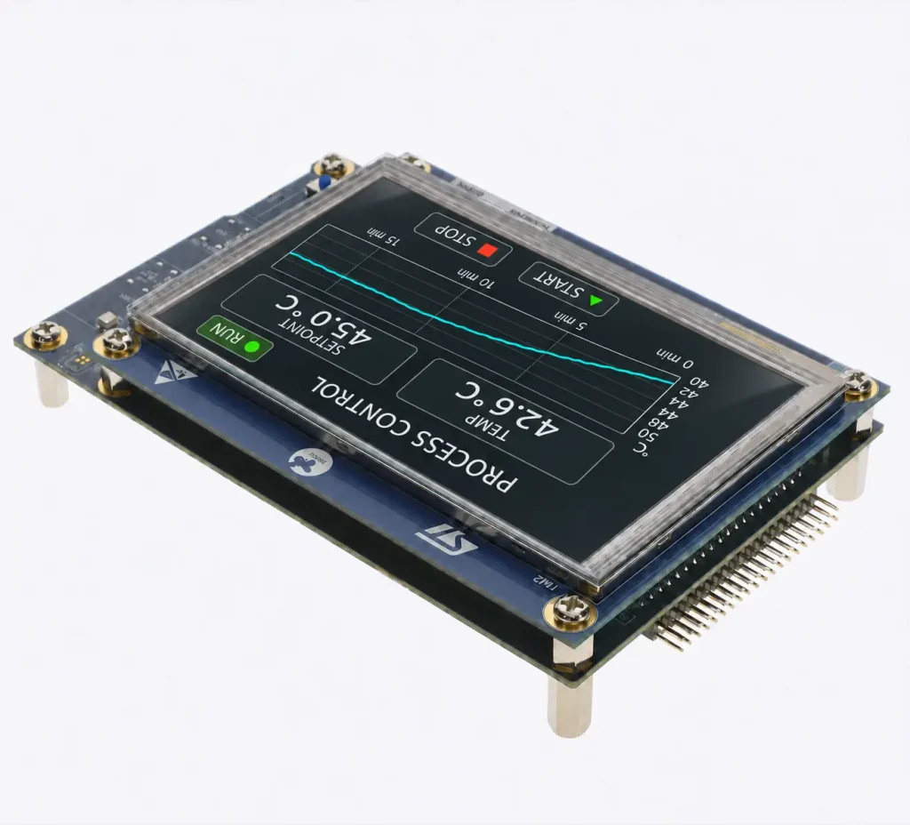
Choose an STM32 display interface by checking the full MCU part number and package, then working out how many pixels your application must move and how often. SPI and 8080-style modules with their own display memory suit interfaces that update in regions. Parallel RGB and MIPI DSI video mode stream pixels continuously. For an industrial control panel, a few changing readings and a full-screen trend animation can lead to different interface choices at the same resolution.
1. Check the MCU and package before choosing the interface
Start with the ordering code on the bill of materials. Use the STM32 datasheet and alternate-function tables to confirm which signals reach the selected package. An MCU may have an LCD-TFT display controller (LTDC) while the chosen package exposes fewer RGB data lines than the panel needs. Check pin conflicts with other board functions, then use the reference manual to see which memory regions the display and graphics peripherals can access. Before assigning a framebuffer address, check that LTDC can read that RAM region and that the graphics engine can access it if your design uses one.
For an STM32 TFT display, check where the image is stored. A module with graphics RAM (GRAM) keeps the current image while the MCU writes a changed region. A parallel RGB panel still needs a pixel stream when the screen shows the same image for minutes at a time.
| Interface | When it fits | What the STM32 needs | Common integration trap |
|---|---|---|---|
| Serial Peripheral Interface (SPI) | A controller-based module with small or infrequent updates, such as status indicators and numeric readings. | SPI plus the module’s control signals. Direct memory access (DMA) can offload transfers. | DMA frees CPU time, but the wire rate still limits how fast a large area can be redrawn. |
| FMC/FSMC 8080 parallel | A module with GRAM that accepts 8- or 16-bit 8080 writes, where SPI throughput is insufficient. | Flexible Memory Controller (FMC) or Flexible Static Memory Controller (FSMC), with compatible asynchronous bus timing and enough pins. | A wrong command/data address mapping or write pulse width can leave the panel unresponsive. |
| Parallel RGB via LTDC | A panel with a continuous RGB display interface, where the MCU can sustain scanout from memory. | LTDC pins for data and timing, a valid pixel clock, and memory accessible to LTDC. | The image may work on a static test screen and show corruption once rendering and scanout compete for memory. |
| MIPI Display Serial Interface (DSI) | A DSI panel whose operating mode and lane requirements match the host, particularly where parallel RGB routing is impractical. | A DSI host and its physical interface for a direct connection. Video mode uses LTDC as the pixel source on supported STM32 parts. | Matching lane count alone leaves lane rate, pixel format, operating mode and startup commands to verify. |
2. Budget framebuffer capacity and traffic separately
For an 800 × 480 STM32 display using RGB565, each pixel takes two bytes in memory. A tightly packed display framebuffer is 800 × 480 × 2 = 768,000 bytes, or 750 KiB. Two full buffers take 1,500 KiB. Those figures exclude any stride padding, additional layers, GUI assets, stacks and heap. Work out which assets stay in flash and which need RAM during rendering.
At 60 Hz, one full-screen RGB565 layer consumes about 46.1 MB/s of average active-image reads for scanout alone. This calculation excludes rendering writes, blending reads and bus overhead. Double buffering adds storage and lets software draw into a separate buffer while LTDC scans the current one. Swap at vertical blanking to avoid a mid-frame change. Check sustained memory performance with the busiest screen and other DMA traffic running together.
Calculate the RGB pixel clock from total horizontal pixels × total vertical lines × refresh rate. Each total includes the active image, front porch, sync width and back porch. Use the panel datasheet’s timing limits. For an STM32 display on SPI or 8080, estimate bytes transferred per changed region, then measure how long that region takes to send with the actual command and transfer overhead.
3. Check these details before swapping panels
Two panels with the same diagonal and resolution can need different wiring and firmware. Review the exact module revisions side by side before connecting a replacement STM32 display.
- Connector: Confirm pitch, contact side, pin numbering and each signal assignment.
- Power and logic: Match the supply rails, power sequence, reset timing and input voltage thresholds.
- Commands or timing: Check the controller’s startup sequence for command-driven panels. For RGB, check data order, clock edge, sync polarities and data-enable behavior against the timing diagram.
- Backlight: Confirm LED string voltage and current, driver topology, enable polarity and dimming input.
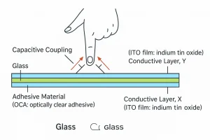
- Touch: Identify the touch controller and confirm its bus, address where applicable, interrupt and reset wiring, and coordinate mapping.
Frequently asked questions
Can an STM32 drive a TFT without a full framebuffer in MCU RAM?
Yes, an SPI or 8080 module with its own GRAM can retain the image while the STM32 renders and sends small regions from a scratch buffer. With a continuously scanned RGB panel, LTDC still needs a valid pixel source for the configured layer throughout scanout.
Is a 60 Hz panel refresh the same as 60 GUI updates per second?
A 60 Hz panel refresh means the panel scans an image 60 times per second. New GUI frames arrive only as fast as software can render and transfer them. A static screen can be scanned repeatedly, while an animation can expose rendering delays or memory contention.
Does RGB565 framebuffer storage require a 16-bit RGB connector?
No. RGB565 describes how pixels are stored in memory. The LTDC output and the panel wiring determine the physical RGB bus. Check the MCU’s output color mapping and the panel’s required input bits before choosing which lines to route. Verify the result with red, green and blue test patterns.
A documented Rocktech and STM32 pairing
ST’s UM3223, section 8.5, documents the STM32U5G9J-DK2 with an MB1860 display board carrying Rocktech’s 5-inch, 800 × 480 RK050HR18-CTG. The board connects to the STM32U5G9ZJT6Q’s parallel RGB interface through CN3. That compatibility is specific to the documented board and configuration. Rocktech’s earlier guide to TFT modules for STM projects covers other pairings. Use the Discovery kit as an STM32 display reference for pin mapping and bring-up, then verify your own package, timing, memory and wiring before committing the schematic.