1. Introduction: Why the RGB Interface Still Matters
In many recent design reviews and project discussions, I noticed that engineers often jump straight to MIPI DSI, LVDS, or even HDMI when talking about TFT LCD interfaces.
However, in a large number of industrial, medical, and embedded products, the classic parallel
RGB interface is still the workhorse that drives the main display.
In most of our embedded projects, the RGB interface is still a direct, pixel-by-pixel connection between the SoC and the TFT panel, without any complicated conversion layers in between.
It is simple, well understood, and easy to debug with an oscilloscope or logic analyzer.
For resolutions like 480×272, 800×480, 1024×600, or even 1280×800, it remains a very cost-effective choice.
In the following sections, I’ll walk through how the TFT LCD RGB interface actually works in real designs, which signals it uses, how timing is defined,
and in which applications it is still the most practical option.
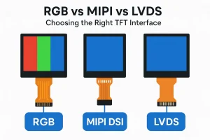
We will also compare it with MIPI, LVDS, and other display interfaces so that you can choose the right solution for your next design.
2. Basic Concepts of the TFT LCD RGB Interface
2.1 What Does RGB Mean?
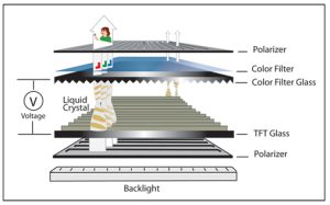
As everyone in the display industry knows, RGB simply refers to Red, Green, and Blue—the three building blocks behind almost every color you see on a TFT screen.
Each pixel of a TFT LCD is made up of three sub-pixels (R, G, and B). By driving each sub-pixel with a specific intensity,
the panel can reproduce a wide range of colors.
In an RGB interface, the display controller outputs the color value for each pixel as a set of digital signals.
The LCD timing controller (TCON) inside the panel receives these values in sync with the pixel clock and refreshes the pixel matrix line by line.
2.2 Parallel RGB vs. Serial Interfaces
The RGB interface is a parallel interface:
for every pixel clock, several bits for red, green, and blue are output simultaneously on different data lines.
From my experience, this feels very different from interfaces like MIPI DSI or eDP, which behave more like high-speed data links than simple pixel buses.
Parallel RGB is electrically simpler, but it requires more pins and more PCB traces.
This makes it ideal for short-distance connections between an SoC and a local TFT panel on the same board or within the same enclosure.
3. Signal Set of a TFT LCD RGB Interface
3.1 Color Data Lines
Depending on the required color depth, TFT LCDs with RGB interfaces usually support one of these common formats:
| Format | Total Bits | Bits per Color | Typical Name |
|---|---|---|---|
| RGB565 | 16-bit | R:5, G:6, B:5 | High-color (65K colors) |
| RGB666 | 18-bit | R:6, G:6, B:6 | 262K colors |
| RGB888 | 24-bit | R:8, G:8, B:8 | True-color (16.7M colors) |
In real products, the jump from RGB565 to RGB888 is most noticeable on UI gradients and camera previews, although it also increases pin count and routing pressure on your PCB.
For example, a 24-bit RGB888 interface needs 24 parallel data pins R0..R7, G0..G7, B0..B7.
3.2 Control and Synchronization Signals
In addition to the color data lines, several digital control signals define the timing:
- PCLK (Pixel Clock): Each rising or falling edge (depending on configuration) latches one pixel worth of RGB data.
- HSYNC (Horizontal Sync): Indicates the start of a new line (row) of pixels.
- VSYNC (Vertical Sync): Indicates the start of a new frame of pixels.
- DE (Data Enable): Marks valid pixel periods within a line. When DE is low, the controller outputs blanking data.
Depending on the panel, either HSYNC/VSYNC/DE are used together, or the panel is configured to use only DE and PCLK with internal timing.
In practice, always double-check the panel datasheet—especially the signal polarities—because different suppliers are rarely 100% consistent.
4. How the RGB Interface Works: Timing Principles
4.1 Line and Frame Scanning
In reality, TFT LCDs are refreshed in a very fixed scanning sequence:
- The controller outputs pixel data for the first line, synchronized with PCLK.
- At the end of the visible pixels for that line, additional clock cycles are added for the horizontal front porch, sync pulse, and back porch.
- HSYNC marks the transition to the next line.
- After all lines of the frame are transmitted, VSYNC marks the start of a new frame.
This entire sequence repeats at the configured frame rate, typically 50–60 Hz for industrial displays.
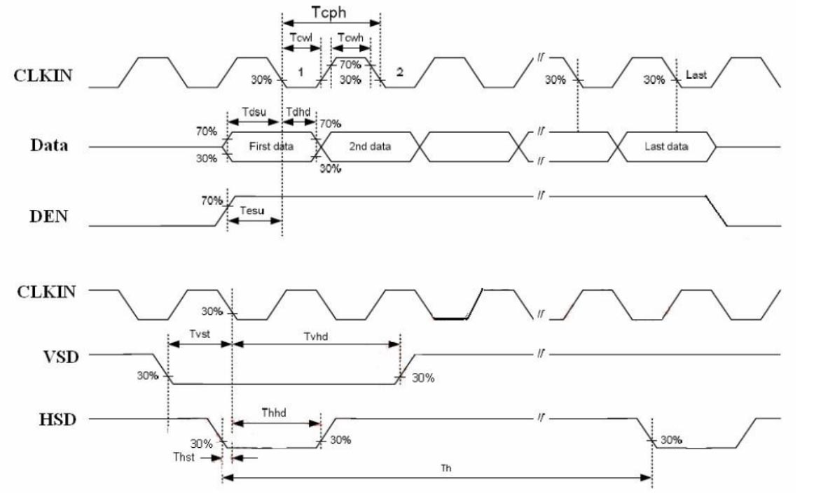
4.2 Important Timing Parameters
For each direction (horizontal and vertical), the timing is divided into four parts:
- Visible area: The number of active pixels (for example 800 pixels for an 800×480 display).
- Front porch: Idle clocks after the visible pixels at the end of a line or frame.
- Sync pulse: Active period of HSYNC or VSYNC.
- Back porch: Idle clocks before the visible pixels of the next line or frame.
The total number of pixel clocks per line is:
Htotal = Hactive + Hfront + Hsync + Hback
The total number of lines per frame is:
Vtotal = Vactive + Vfront + Vsync + Vback
Once these values are known, the required pixel clock can be estimated as:
Pixel Clock ≈ Htotal × Vtotal × Frame Rate
For example, an 800×480 panel with typical timing values and a 60 Hz refresh rate usually requires a pixel clock in the range of 30–33 MHz.
5. Connecting the RGB Interface to a Microcontroller or SoC
5.1 Typical Hardware Architecture
In an embedded design, the TFT panel is usually connected directly to the display controller inside an ARM-based SoC or an MCU with an LCD-TFT controller.
The basic connections include:
- RGB data lines:
R0..R7,G0..G7,B0..B7(depending on color depth) - Control lines:
PCLK,HSYNC,VSYNC,DE - Reset and power control:
RESET,STBY, and related signals - Backlight control: PWM or enable pin for LED backlight driver
Often an additional serial interface such as I²C or SPI is used to configure the panel’s power sequences or gamma settings.
5.2 PCB Layout Considerations
If you’ve ever routed a 24-bit RGB interface at 30–40 MHz, you already know how unforgiving the PCB layout can be:
- Keep trace lengths matched within each group (R/G/B buses and clock/sync lines).
- Route PCLK with extra care and keep it as short and clean as possible.
- Provide a continuous ground reference plane to reduce EMI and crosstalk.
- Use series termination resistors if required by the SoC or panel datasheet.
Good layout minimizes signal integrity problems such as ghosting, random noise, or intermittent display issues.
6. Pros and Cons of the RGB Interface
6.1 Advantages
- Low latency: Pixel data goes straight from your SoC to the panel, which is especially useful for HMIs or camera preview applications.
- Simple protocol: No complex encoding or high-speed PHY required. Ideal for MCUs and low-cost SoCs.
- Easy debugging: Signals can be inspected with standard oscilloscopes or logic analyzers.
- Low BOM cost: No extra bridge ICs or serializer/deserializer pairs.
6.2 Disadvantages
- Many pins: A 24-bit RGB interface easily consumes more than 30 pins including control lines.
- Limited cable length: Parallel single-ended signals are sensitive to noise and skew, so RGB is best for short distances.
- Higher EMI: Multiple simultaneous switching lines increase electromagnetic emission compared with differential serial links.
- Scaling to high resolution is difficult: For resolutions like Full HD or higher, pixel clock and pin count become impractical.
7. RGB Interface vs. Other Display Interfaces
7.1 RGB vs. MIPI DSI
- MIPI DSI uses high-speed differential lanes and packet-based transmission, enabling very high resolutions with fewer pins.
- It requires a more complex PHY and is harder to debug without specialized tools.
- RGB is better suited for simple industrial designs; MIPI is preferred for smartphones, tablets, and compact consumer products.
7.2 RGB vs. LVDS
- LVDS also uses differential signaling and serializers to transmit RGB data over fewer pairs.
- It is widely used for laptop and larger industrial panels, especially 10.1″ and above.
- Compared with LVDS, native RGB panels remove the need for an LVDS transmitter but require more pins on the SoC.
7.3 RGB vs. HDMI / DisplayPort
- HDMI and DisplayPort are mainly external interfaces for TVs, monitors, and consumer AV devices.
- They are overkill for most embedded products that have the panel mounted only a few centimeters away from the board.
- Internally, even HDMI monitors often convert the signal back to LVDS or eDP to drive the LCD matrix.
8. Real-World Application Examples
The RGB interface remains widely used in many embedded and industrial systems, especially where robustness, long-term availability, and design transparency are more important than extreme cable length or ultra-high resolution.
Typical applications include:
- Industrial HMIs (Human–Machine Interfaces): operator panels on production lines, PLC control panels, and factory terminals.
- Medical equipment: bedside monitors, diagnostic devices, portable analyzers.
- Smart home and building automation: wall-mounted control panels for lighting, HVAC, and security.
- Embedded Linux appliances: network devices, gateways, or control units with a small front display.
In these products, resolutions between 480×272 and 1280×800 are often sufficient, and the direct RGB connection keeps both hardware cost and software complexity low.
9. Debugging and Common Issues
9.1 Common Problems I Have Seen in Real Projects
- No image / white screen: power-up sequence, reset line, or backlight not correctly controlled.
- Shifted or wrapped image: horizontal/vertical timing parameters do not match panel datasheet.
- Wrong colors: incorrect mapping of RGB bits or wrong color format (RGB565 vs RGB888).
- Flicker or noise: poor signal integrity, pixel clock too high, or insufficient grounding.
9.2 Practical Debugging Tips
- In most of my debugging sessions, I start with a known working timing configuration from either the panel vendor or an existing reference board.
- Verify PCLK, HSYNC, VSYNC, and DE waveforms with an oscilloscope.
- Reduce pixel clock and frame rate during debugging to add timing margin.
- Check that the panel’s power rails and LED backlight supply meet the specified sequence and levels.
10. Will the RGB Interface Disappear?
From a technology roadmap perspective, high-resolution consumer products have already moved away from parallel RGB in favor of MIPI DSI, LVDS, and eDP.
However, in the embedded and industrial world, designs live much longer than smartphones or laptops.
Many HMI platforms remain in production for 5–10 years or more, and during this time the stability and transparency of the RGB interface are significant advantages.
For new designs, the decision is mostly about trade-offs:
- If you need a compact connector, long cable, or very high resolution, a serial interface like MIPI or LVDS is usually better.
- If your design is board-level, resolution is moderate, and cost and simplicity matter, the TFT LCD RGB interface is still an excellent choice.
11. Conclusion
The TFT LCD RGB interface might look old-fashioned compared with modern high-speed serial links,
but it remains one of the most practical and reliable ways to connect an embedded processor to a display.
By understanding its signals, timing parameters, and PCB layout requirements,
engineers can build robust and cost-effective systems that deliver exactly the image quality their application needs.
Rather than being replaced overnight, the RGB interface continues to coexist with MIPI, LVDS, HDMI, and other technologies.
Choosing the right interface is ultimately about choosing the right compromise between pin count, complexity, resolution, and product lifetime.
For many embedded systems, RGB is still the most balanced option.