Touchscreen TX/RX channel count is one of the first items we check when laying out a custom capacitive touch sensor. If the controller does not provide enough channels, the problem cannot be corrected later by firmware tuning. If it provides far more channels than the sensor needs, the design may carry unnecessary cost and routing complexity.
The channel count determines how many sensor electrodes a touch controller can scan. The available channels set a practical limit on the sensor matrix. They also determine whether all electrode traces can be routed into the available FPC tail without making the border unnecessarily wide. One point that regularly causes confusion is multi-touch. A controller specified for 32 RX channels is not a “32-point touch” controller. The number of simultaneous fingers is a separate controller and firmware specification.
For most projects, there is no advantage in choosing the controller with the largest number of channels. In practice, we estimate the sensor matrix before fixing the controller. That gives us the required TX/RX count and some spare capacity for layout adjustment. We can then check which Ilitek or Goodix device fits the electrical and mechanical constraints.
What Does Touchscreen Channel Count Mean?
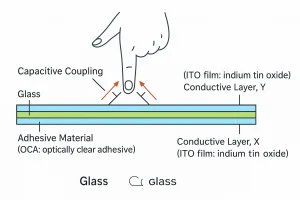
In a mutual-capacitance sensor, one electrode group is driven by the controller and the other is measured. These groups are normally identified as TX and RX. Their intersections form the sensing matrix used to locate a finger. A finger changes the mutual-capacitance signal at several nearby intersections. The controller compares those measurements with its baseline data and derives an X/Y coordinate. The controller processes these changes and calculates the touch position.
An 18 TX × 32 RX sensor has 576 possible TX/RX intersections. Those intersections are measurement nodes, not display pixels and not individual touch points. This does not mean that the touchscreen has a display resolution of 18 × 32 or that it can detect 576 fingers. The controller uses signal data from several nearby intersections to estimate a much more precise coordinate.
| Term | What It Describes | Example |
|---|---|---|
| TX channels | Electrodes that transmit the scanning signal | 18 TX |
| RX channels | Electrodes that receive capacitance changes | 32 RX |
| Sensing intersections | Locations formed where TX and RX electrodes cross | 18 × 32 = 576 |
| Touch points | Fingers that can be reported at the same time | 5-point or 10-point touch |
Therefore, both specifications are needed when reviewing a controller: the available TX/RX channels determine whether the sensor can be connected, while the supported touch-point count describes how many contacts the firmware can report simultaneously.
How Many TX/RX Channels Does a Touchscreen Need?
We cannot assign a reliable TX/RX count from the LCD diagonal alone. A 7-inch touchscreen from one project may use a different TX/RX configuration from another 7-inch touchscreen because the aspect ratio, border width, electrode pitch, and FPC position are different.
After the touch active area is fixed, we select an initial electrode pitch and pattern. The matrix is then adjusted for edge performance, trace routing, FPC width, and the channel capacity of the candidate controller. Reducing electrode pitch usually increases the required channel count, but it does not guarantee better coordinates. Poor electrode geometry, an unstable baseline, or LCD noise can cancel out the expected improvement.
LCD resolution should not be used to calculate touchscreen channel count. An 800 × 480 LCD does not need 800 TX and 480 RX electrodes. The display pixels produce the image; the touch controller estimates coordinates from a much coarser sensing grid and reports those coordinates to the host processor.
The aspect ratio also changes the balance between TX and RX. A wide landscape panel normally needs more electrode lines along its longer dimension. A narrow border can make the design harder because every sensor trace must reach the tail area without creating excessive dead zones or uneven sensitivity.
| Design Condition | Effect on TX/RX Planning |
|---|---|
| Larger active area | May require additional channels to maintain suitable electrode spacing |
| Wide or portrait aspect ratio | Changes the required balance between TX and RX channels |
| Narrow border | Leaves less room for routing electrodes to the FPC |
| Thick cover glass | Reduces the measured touch signal and may require sensor tuning |
| Glove or wet operation | Requires controller features and firmware to be evaluated on the real assembly |
I would avoid selecting a controller whose TX/RX limits exactly match the first sensor draft. Even a small change to the active area, edge electrodes, or FPC routing can require another line. One or two spare channels on the constrained axis can prevent a controller change later. A small amount of unused capacity is usually helpful, but choosing a much larger controller without a reason can increase cost and complicate sourcing.
Choosing an Ilitek or Goodix Touch Controller
Rocktech commonly works with Ilitek and Goodix touch controllers. We use both Ilitek and Goodix devices, but we do not select between them at brand level. The comparison is made between exact controller part numbers after the preliminary sensor matrix is available.Selection therefore needs to be made by exact part number rather than by manufacturer alone.
The controller must provide at least the number of TX and RX channels required by the sensor layout. The package must also suit the FPC design, and its supply voltage and host interface must match the customer’s main board. I2C is common in embedded display projects, but the address, interrupt behavior, reset timing, and power-up sequence still need to be checked.
Firmware is part of the touchscreen design. Controller settings are tuned for the actual sensor pattern, cover-glass thickness, LCD noise, grounding, and intended use conditions. Reusing a firmware file from another sensor may appear to work on the bench, yet still produce edge errors, coordinate drift, false touches during charging, or missed input through thick cover glass. The configuration should be tuned and validated on the final sensor stack-up.
Similar channel counts do not make two Ilitek or Goodix controllers drop-in replacements. A controller change can affect the FPC pinout, host driver, sensor tuning, and production firmware. Changing the controller may require a new FPC layout, host-driver changes, sensor tuning, and another round of system testing.
How Rocktech Selects a TX/RX Configuration
For a custom Rocktech touch panel, the first useful documents are the LCD drawing and the customer’s cover-lens drawing. From these, we can identify the touch active area, border available for electrode routing, FPC exit position, and connector constraints. The LCD outline, active area, cover-lens drawing, visible area, FPC location, and connector direction are reviewed before the touch sensor is laid out.
We normally make a preliminary electrode layout before choosing the final controller. The layout shows which axis is likely to reach its channel limit and whether the traces can enter the proposed FPC tail. At that point, suitable Ilitek and Goodix part numbers can be compared on real constraints rather than nominal screen size.The choice also considers touch-point requirements, communication interface, cover-glass construction, operating environment, firmware support, and component availability.
A sample should be tested with the actual LCD and host board whenever possible. This is particularly important when the touch sensor is bonded to an lvds lcd. Although LVDS uses differential signaling, noise from the panel power rails, DC/DC converters, backlight circuit, and ground return path can still affect touch measurements. A sensor that works correctly on an open bench may produce false touches after the charger is connected or the assembly is installed behind a metal bezel.
Frequently Asked Questions
Does a larger touchscreen always need more channels?
Usually, a larger active area needs more sensing coverage, but screen size alone is not enough to determine the channel count. Aspect ratio, electrode pitch, border width, sensor pattern, and controller algorithms also affect the final TX/RX configuration.
Can Rocktech calculate the channel count for my touchscreen?
Yes. Rocktech can review the touch active area, cover-lens drawing, FPC position, environmental requirements, and host interface, then recommend a sensor layout and a suitable Ilitek or Goodix controller for evaluation.
Should I choose Ilitek or Goodix for my project?
The decision should be based on the exact controller model, required TX/RX capacity, touch-point count, electrical interface, firmware support, package, and supply requirements. Rocktech can compare suitable options after reviewing the complete touchscreen specification.
Can one touch controller be reused for a different screen size?
Possibly, if it has enough channels and supports the new sensor design. However, the electrode layout and firmware normally need to be reviewed again. Reusing an existing firmware configuration without testing may produce weak edge response or unstable touch detection.
What should I send Rocktech to start a touchscreen evaluation?
Send the LCD specification, touch active area, cover-glass drawing and thickness, required number of touch points, host interface, operating environment, connector requirements, and estimated order volume. A host-board schematic or connector pinout is also useful when available.