Introduction: More Than Just Glue Between Layers
In many design reviews I’ve been part of, someone eventually describes optical bonding as simply ‘sticking the glass onto the LCD.’ It sounds reasonable at first, but anyone who has actually debugged optical issues knows there’s much more going on. In reality, it is a carefully engineered optical stack that directly changes how light travels through the display. The way we perceive brightness, contrast, and clarity – especially in bright ambient light – is strongly influenced by the interfaces between glass, air, adhesives, and polarizers.
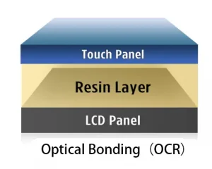
Traditional displays usually have an air gap between the cover glass or touch sensor and the LCD module. The structure is inexpensive and straightforward to build, but in real products it often adds more reflective surfaces than you’d expect. Optical bonding removes this air gap and replaces it with an optically clear adhesive (OCA) or resin. To see why removing that tiny gap has such a big impact, it helps to look briefly at the underlying physics – mainly refractive index, Fresnel reflections, and contrast ratio.
The Root Cause: Air Gaps and Internal Reflections
Think about a very typical air-gap stack: a cover glass on top, a thin pocket of air underneath, and the LCD cell below that. Whenever light moves from one medium to another – for example from glass to air or air to glass – part of it is reflected. In an air-gap structure, there are at least two strong interfaces:
-
- Glass → Air
- Air → LCD top polarizer
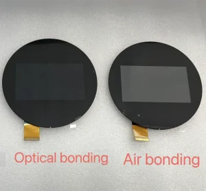
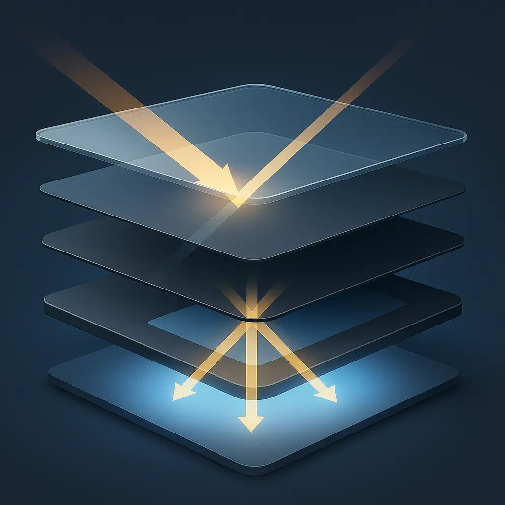
Ambient light hitting the front surface of the display is partly reflected immediately. Another portion enters the glass, reaches the air gap, and is reflected again at that internal interface. What the user actually sees is the combination of all those reflections: more glare, blacks that look grey, and sometimes a faint “double image” around bright objects. The more interfaces we have, the more opportunities light has to bounce back toward the viewer instead of reaching the LCD or being absorbed by it.
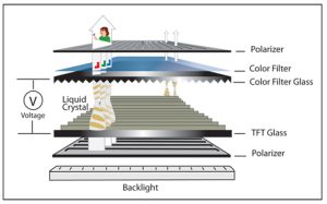
Refractive Index Basics: Glass, OCA, Air, and LCD Layers
The strength of reflection at a boundary depends mainly on the refractive index of the two materials. The refractive index n describes how much light slows down inside a medium compared to vacuum. Typical values in a display stack are:
| Material | Approx. Refractive Index (n) |
|---|---|
| Air | 1.00 |
| Optically Clear Adhesive (OCA) | 1.41 – 1.48 |
| Cover glass / cover lens | 1.50 |
| Top polarizer / LCD surface | 1.50 – 1.52 |
Once you line up the numbers, the problem is pretty easy to spot: air has a refractive index of roughly 1.0, while glass and polarizers sit close to 1.5. This large mismatch creates strong reflections at any glass–air boundary. OCA is deliberately formulated with a refractive index close to glass and the polarizer films, so the transitions between those layers are much smoother and far less reflective.
Fresnel Reflections: How Much Light Is Lost at Each Interface?
Reflection at a boundary is described by the Fresnel equations. You don’t need the full derivation here – the only thing that matters is that the reflectance at normal incidence between two media with indices n₁ and n₂ is roughly:
R ≈ ((n1 − n2) / (n1 + n2))²
For a glass–air interface (n ≈ 1.5 and 1.0), this gives a reflection of about 4% at each surface. Two surfaces – glass → air and air → polarizer – already mean nearly 8% of the light is lost or sent back as reflections. In reality, with angled light and multiple passes, the perceived loss can be even higher.
When we replace the air gap with OCA (n ≈ 1.45) between glass (n ≈ 1.5) and polarizer (n ≈ 1.5), the difference in refractive index is very small. The same formula now produces a reflectance well below 1%. That, in simple terms, is why a properly bonded stack shows far less internal reflection than an air-gap design.
How Optical Bonding Removes Multi-Surface Reflections
In a bonded stack, the structure becomes:
- Cover glass
- OCA (optically clear adhesive)
- LCD top polarizer
There is no longer a low-index air gap to create high-contrast interfaces. The light encounters materials whose refractive indices are well matched, so most of it passes through rather than bouncing around inside the stack.
In day-to-day use, this shows up as:
- Less mirror-like reflection of room light or sunlight.
- Fewer “halos” or ghost outlines around bright objects in the scene.
- And, importantly, more of the backlight output ends up as useful image light instead of being bounced back and forth inside the stack.
In some designs, optical bonding can effectively increase usable brightness by 10–20% without changing the backlight at all. Conversely, the same readability can be achieved with a lower-power backlight, improving power consumption and thermal behavior.
Display Contrast: The Real Metric for Outdoor Visibility
When discussing outdoor readability, many datasheets advertise maximum brightness in nits, but brightness alone is not the most important metric. What really matters is contrast ratio under ambient light conditions.
In its simplest form, contrast ratio can be written as:
CR = Lon / Loff
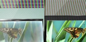
where Lon is the luminance of a white pixel and Loff is the luminance of a black pixel. Reflections from the front surface and internal interfaces add light to both states but are especially visible when the LCD tries to show black. The perceived black level is lifted, turning deep blacks into grey and shrinking the contrast ratio.
By reducing reflections from multiple interfaces, optical bonding lowers the stray light component that reaches the viewer. The result is a higher effective contrast ratio in real environments – particularly outdoors or under strong indoor lighting. That’s why, in real products, a bonded display with a modest backlight can still look clearer than an air-gap design that drives the LEDs much harder.

Parallax and Touch Accuracy: Geometry Meets Optics
One more side effect of the air gap shows up as parallax. When the cover lens sits several millimeters above the LCD image plane, viewing the display at an angle causes the apparent position of the pixel to shift relative to the point where the user touches. For basic touch targets it’s mostly just a small nuisance, but for precise gestures—or stylus use—it can noticeably affect accuracy. but for precise touch gestures or stylus operation it can become a significant usability problem.
Optical bonding pulls the touch sensor or cover glass much closer to the image plane, effectively reducing the optical distance between finger and pixel. Even though the glass may still be physically thick, the removal of the air gap reduces refraction effects and visual displacement. The interaction feels more “direct”, as if your finger is on the pixels themselves instead of on a piece of glass hovering above them.
Mechanical Behavior: An Optical Stack That Acts as One Piece
Even though the discussion so far has been mostly about optics, the mechanical behavior of the stack is tied to the same layers. When the cover glass is only mechanically fixed at the edges and separated from the LCD by air, the two parts can flex independently. Vibrations, shocks, and drops may cause the glass to resonate or crack.
Optically bonding the glass to the LCD with a layer of adhesive effectively turns the two into a single laminated structure. Mechanically, the whole assembly starts to behave much more like a single solid plate, with higher stiffness and better impact resistance. This makes it easier to reach demanding robustness levels such as IK ratings or automotive vibration requirements, without resorting to overly thick glass that would compromise touch sensitivity.
Optical Artifacts: Newton Rings, Mura, and Bubbles
When the bonding is done well, the display looks dramatically better. When it is not, the process can introduce its own set of visual defects – most of which still come down to basic optics.
- Newton rings: These concentric rainbow or dark rings occur when two surfaces are very close but not perfectly parallel, creating a varying air or adhesive thickness. In that situation the thin film acts like a simple interferometer, so constructive and destructive interference show up as visible rings.
- Mura: Non-uniform adhesive thickness or incomplete wet-out can change the local transmission, leading to blotches or brightness variations that are most visible on uniform grey backgrounds.
- Bubbles and particles: Any trapped air or dust creates localized interfaces with strong refractive index mismatch. Under certain angles they can act like tiny lenses or bright defects.
Avoiding these artifacts requires not only clean-room conditions and precise lamination equipment, but also a good understanding of how adhesive viscosity, cure schedule, and glass flatness influence the final optical path.
OCA vs OCR: Different Materials, Different Optical Behavior
In most industrial displays, the adhesive layer is either an OCA (Optically Clear Adhesive) film or a liquid resin often called OCR or LOCA. From a practical physics point of view, both types of material need to offer high transmission, low haze, and a refractive index close to the surrounding glass and polarizer layers. However, there are differences:
- OCA films have very stable thickness and refractive index. Because they are pre-formed, they offer excellent uniformity and are well suited to small and medium-sized panels.
- Liquid resins can fill complex shapes or cover large areas more easily, but controlling thickness and avoiding flow-related mura is more challenging.
For the optical designer, the key is making sure that whichever material is chosen, its refractive index remains close to the surrounding layers over the full operating temperature range. If the index drifts too much, reflections and contrast loss reappear.
Applications Where the Physics Demands Optical Bonding
Of course, not every product really needs optical bonding – many low-cost indoor devices work perfectly well with a simple air-gap structure. But in many fields the physics makes bonding almost mandatory:
- Outdoor industrial HMIs: Sunlight reflection and low contrast can render air-gap screens unreadable. Optical bonding improves contrast and reduces glare, enabling operators to read data safely.
- Medical imaging and monitors: Radiologists and clinicians rely on subtle grayscale differences. Any reflective haze or parallax is undesirable.
- Automotive and transportation: Cockpit displays must remain legible in bright sunlight and under vibration. Bonded stacks deliver both optical and mechanical benefits.
- Smart home control panels and premium consumer products: Even when the environment is not extremely harsh, the crisper image and “ink on glass” feeling of bonded displays creates a noticeably higher-end user experience.
Conclusion: Optical Bonding as an Optical Design Tool
In many project discussions, optical bonding is still treated as a simple checkbox – “air gap” versus “full bonding”. After working with multiple display designs, I’ve come to see optical bonding less as a checkbox and more as a design decision that shapes both performance and user experience. By controlling refractive indices, eliminating air gaps, and simplifying the optical path, a bonded display dramatically reduces reflections, boosts contrast ratio, improves touch accuracy, and increases mechanical robustness.
In reality, it is much closer to an optical design decision than a mere manufacturing add-on. Engineers who understand the underlying physics can decide when the benefits justify the additional process cost and can specify the right adhesive, glass thickness, and bonding method for their application. As expectations for display quality continue to rise in industrial, medical, and embedded systems, this understanding becomes a powerful tool for building screens that perform reliably in the real world, not only in the datasheet.