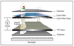
Flexible printed circuits (FPCs) are common in the current world of compact electronics, particularly in small-to-medium TFT displays, embedded systems-on-a-board, handheld terminals, internet of things, smart appliances, and industrial controls. With its products acquiring thinner outlines and more modular designs, TFT FPC design has turned out to be a significant discussion among the hardware designers and system integrators.
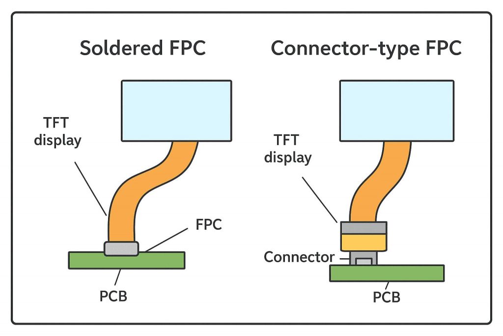
Two most common types of FPC are Soldered FPC and Connector-type FPC among other FPC designs. Both are used to connect a TFT display module to a main board or driver board, although the two are different in design, assembly, ease of re-work, and the application.
1. What Is a Soldered FPC?
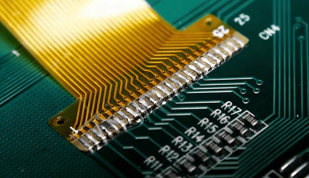
A Soldered FPC refers to a flexible circuit whose tail is directly soldered to a PCB, usually through SMT reflow or manual soldering during development.
1.1 Electrical Characteristics
Because the FPC is bonded directly to the PCB pads:
-
Contact interface is hard and firm.
-
Other parasitic components brought out by connectors are prevented.
-
The controlled impedance can be held more precisely over the high speed lanes.
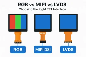
For common TFT display interfaces such as MIPI DSI, RGB 18/24-bit, LVDS, or even lower-speed interfaces like SPI, a direct solder joint typically provides predictable electrical behavior. That is why Soldered FPCs tend to be employed in the devices that follow high-frequency clocking or sensitive analogue components.
However, the performance differences compared with Connector-type FPCs are often small in practical consumer and industrial applications, unless the design pushes certain signal limits.
1.2 Mechanical and Structural Properties
From a mechanical standpoint:
-
Soldered joints are good at vibration under the condition of reinforcing them with stiffeners.
-
They also remove connector height allowing mechanical stacks to be thinner.
-
It is smaller and is applicable to small TFT module, wearable, or any handheld gadget.
The trade-off is that it is more difficult to rework or resolder a fine-pitch FPC, as the process of deleting and resoldering a fine-pitch FPC takes time and experience
1.3 Common Use Cases
Soldered FPC appears frequently in:
-
Thin consumer electronics
-
Wearables and IoT nodes
-
Compact cameras
-
Handheld medical instruments.
-
Smart home devices
-
Some TFT LCD display modules have fixed tails (COF/COG structure) of FPC.
Such applications tend to emphasize thickness, stable mass-production assembly and a minimized number of components.
2. What Is a Connector-type FPC?
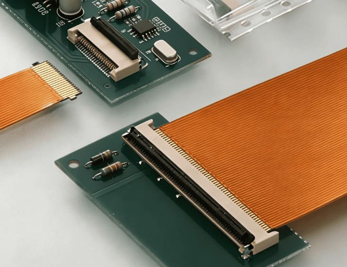
A Connector-type FPC is designed to mate with a ZIF/LIF connector on the PCB. The thickness of the FPC tail is of standard thickness (e.g. 0.2 mm +- tolerance) and is fitted into the connector during assembly.
2.1 Development and Maintenance Benefits
Connector-type FPCs offer:
-
Simple installation– Slot and lock.
-
Simple rework– This is handy in troubleshooting.
-
Flexibility —Screen or touch Module Replacement is without soldering.
-
Convenience in prototyping – Perfect in case of testing various TFT modules by engineers.
This is part of the reason why lots of SBC platforms, ARM boards, RISC-V boards, industrial mini-SBCs, etc., still use connector-based interfaces to display modules.
2.2 Signal Compatibility
The current FPC connectors have many signals associated with displays such as:
-
MIPI DSI
-
LVDS
-
SPI / I²C
-
Capacitive touch controller interfaces (I²C / GPIO)
Connector-type FPCs may introduce minor changes in impedance compared with direct soldering, but these differences are usually manageable if the connector and FPC are designed for the intended interface.
2.3 Typical Applications
Connector-type FPCs are widely used in products that value modularity, repairability, or flexibility in configuration:
-
Development kits
-
Industrial control systems
-
Field-replaceable HMI panels
-
Touch display assemblies
-
Electronics that are used by consumers and need optional display models
Mid-size TFT modules (4.3-10.1 inches) also use connector tails so that they can fit into various mainboards
3. Comparing Soldered FPC and Connector-type FPC
3.1 Electrical Behavior
Soldered FPC
-
Stable interface
-
No connector contact wear
-
Good for high-speed signals (MIPI / LVDS)
Connector-type FPC
-
Contemporary connectors have a high-speed signal management capability
-
Suitable for modular designs
-
Contact reliability depends on connector material and usage cycles
In the majority of their mainstream use cases, both solutions are sufficient, provided that they are correctly designed.
3.2 Mechanical Considerations
Soldered FPC
-
Thinner
-
Better vibration endurance
-
Harder to replace
Connector-type FPC
-
Slightly taller profile
-
Replacement is easy
-
Lifespan of Connector is limited
3.3 Assembly and Production Factors
Soldered FPC
-
Needs to be refined in terms of reflow process
-
Mass production friendly
-
No connector cost
Connector-type FPC
-
Faster manual assembly
-
Convenient for small-batch or prototype builds
-
Connector increases the cost of BOM and spares labour rework
3.4 Design Flexibility
The connector-type FPCs tend to be more flexible in the development and product variations, whereas Soldered FPCs are better suited towards designs that are final and are most efficient in producing products in large quantities.
4. Selecting the Appropriate Approach
Majority of engineers would make a selection based on the practical needs of the product and not on a general principle.
Choose Soldered FPC when:
-
Space is limited
-
Product thickness matters
-
The design is not volatile and will not alter
-
Vibration or mechanical stress is expected
Choose Connector-type FPC when:
-
The replacement or upgrade could be needed
-
It is a modular product or development system
-
Convenience of maintenance is required
-
One product line can be represented in different display versions
The two setups are widespread within the TFT display and the SBC ecosystem.
5. Engineering Engineering Misconceptions and Practical Tips
Misconception 1: Soldered FPC always produces better signal quality.
Reality: Connectors designed for high-speed signals often perform adequately for most display interfaces. Soldering assists, although it is not an entirely exhaustive advantage.
Misconception 2: Connector-type FPC is not durable.
Reality: ZIF connectors with high quality that support 20-50 insertions and above are adequate to most products, particularly those that are not required to be disassembled often.
Misconception 3: Soldered FPC must be chosen for vibration environments.
Reality: Medium vibration can also be used on reality connectors that use locking mechanisms or reinforcement.
Practical Tips
-
For MIPI DSI, check the recommended impedance of the FPC stackup.
-
Use stiffeners for both Soldered and Connector-type FPC tails to improve handling.
-
Confirm tolerance of FPC thickness (common: 0.2 mm) before choosing a connector.
-
In case of doubt, test both the designs first.
6. Conclusion
Two of the most common techniques on the TFT display modules and embedded SBC systems are Soldered FPC and Connector-type FPC. The different methods possess their respective properties regarding their structure, assembly, comfort, and space consumption and one is not necessarily better than another. When engineers are choosing in most projects they are influenced by the practical considerations which are: the thickness of the product required, maintenance requirements, production process and the estimated lifecycle of the device.
The knowledge of the characteristic behavior and trade-offs between the two types of FPC connection allows the development teams to make more informed design decisions without compromising the reliability, maintainability, and compatibility of the systems with the real needs of the actual application.
7. Customized Flexible Circuits and Practical Design Balance
To develop a unique flexible circuit board or a tailored solution, which can be a project with a particular flexible circuit board design or a customer-specific solution, working with a competent partner, such as ROCKTECH makes tailored flexible circuit boards; these can be made to meet an equipments requirement and thus integrated flawlessly and worked dependably.
In this way, the teams will be capable of balancing both practical requirements and design goals, and keep their product flexible to update or adopt variants.