1. Understanding the Material Science of Industrial Displays
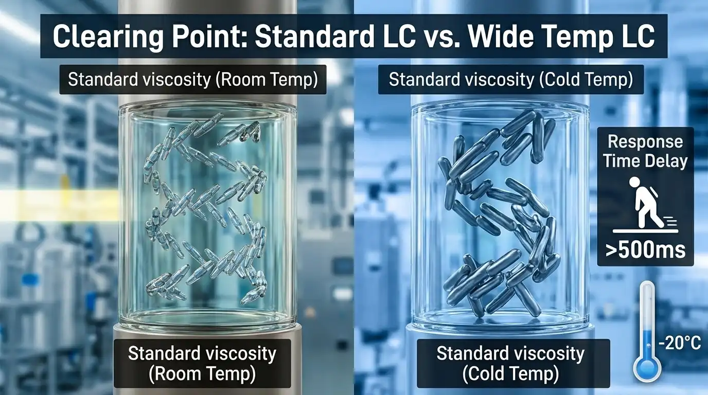
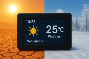
The “Clearing Point” Challenge in TFT Displays
A datasheet specifies the environment where a display can operate, but it doesn’t guarantee stability. In a closed enclosure, the internal temperature of a high-performance unit is often 15°C to 20°C higher than the ambient air due to heat from the CPU, power supply, and the module’s own backlight. If the ambient is 50°C, your display is already pushing 70°C. This is a critical baseline for any Wide Temperature TFT LCD Design.
Rocktech Engineering Insight: The “Wide Temperature” label refers to the specialized Liquid Crystal (LC) Mixture used in the cell. Standard LC mixtures have a high viscosity at low temperatures, leading to a response time (Tr+Tf) that can exceed 500ms at -20°C. Furthermore, every Wide Temperature TFT LCD has a “Clearing Point”—the temperature where the liquid crystal turns into an isotropic liquid and loses its ability to modulate light. Our engineers utilize specialized mixtures with clearing points above 100°C to prevent the “Blackout” effect under heavy solar loading.
2. Critical LCD Thermal Management Strategies: Calculating Heat Loads
To ensure a 10-year lifespan for your hardware, you must implement robust LCD Thermal Management Strategies that go beyond simple ventilation. Many engineers underestimate the thermal impact of the high-brightness backlight. A 1000-nit LED string is essentially a small heater sitting right behind your delicate LC cell.
Engineering Formula for Temperature Rise
For a 7-inch 1000-nits unit, the typical power consumption is around 5W. In a sealed enclosure, you can estimate the temperature rise using LCD Thermal Management Strategies like the simplified thermal model:
ΔT = (P × Rth) / (V × Cp)
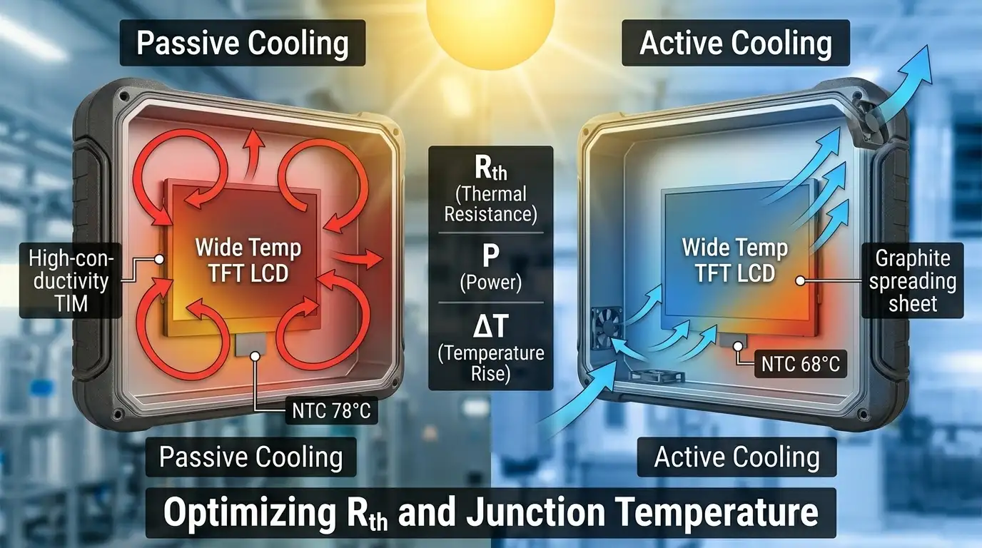
Note on Rth: Rth refers to Thermal Resistance. Think of it as the “traffic jam” heat faces when trying to escape your enclosure. The lower the Rth (by improving contact between the display frame and the metal chassis), the cooler and more reliable your display will be. Reducing Rth is one of the most effective LCD Thermal Management Strategies available during the CAD phase.
Practical Tip: For every 100 nits of brightness added, expect an internal temperature rise of 2°C to 5°C if no active cooling is applied. This is why we recommend “Thermal Throttling” logic in your firmware to dim the backlight if the internal NTC sensor detects temperatures exceeding 75°C. This doesn’t just protect the Wide Temperature TFT LCD; it prevents thermal runaway in the LED driver circuit.
Passive vs. Active Thermal Management
- Thermal Interface Materials (TIM): Use high-conductivity thermal pads between the module’s metal frame and your system’s outer chassis to assist heat dissipation. A 1.5W/m·K pad can often drop the junction temperature by nearly 10°C.
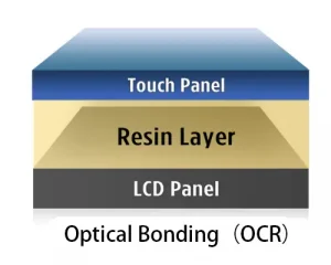
- Optical Bonding (OCA/OCR): This is a cornerstone of Wide Temperature TFT LCD Design, following Society for Information Display (SID) guidelines for contrast and thermal optimization. It creates a solid physical bridge, allowing heat to conduct efficiently from the panel to the front cover glass, effectively turning the glass into a large heat sink.
- Heat Spreading via Graphite: For slim designs where fans are impossible, applying a graphite sheet can help distribute localized “hot spots” across a larger surface area, preventing localized LC clearing.
3. Cold Start Solutions: Beyond -30°C Operation
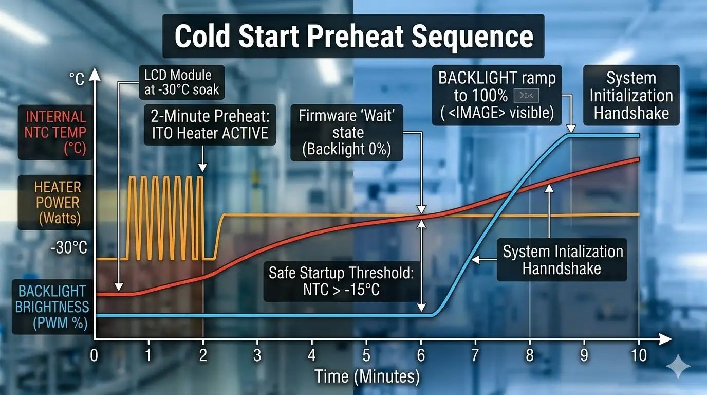
“Cold Start” refers to powering on a display from a -30°C or -40°C soak. This is arguably the most stressful event for an industrial display. Without proper Wide Temperature TFT LCD Design, the sudden voltage spike into a “frozen” driver IC can cause latch-up failures or long-term electrical degradation.
Hardware Integration: ITO Heaters
The most effective way to handle extreme cold is an ITO (Indium Tin Oxide) Heater. By applying roughly 2-4 watts per square inch, you can bring the LC molecules back to a functional viscosity state. However, ensure your power supply can handle the extra current draw during the initial 2-minute heating window of the module. This is a vital component of any extreme-environment Wide Temperature TFT LCD Design.
Software Sequencing and Timing
- The 70% Rule: We often advise customers to wait until the internal temperature reaches -20°C before initializing the full backlight. This prevents “smearing” which can be misinterpreted by the end-user as a hardware defect.
- Staged Startup: Gradually ramp up the backlight brightness via PWM control. This protects the LED strings from thermal shock and prevents the power supply’s voltage from dropping in cold states due to increased resistance in capacitors.
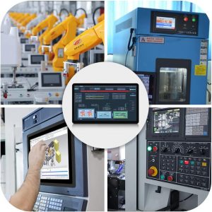
4. Industrial LCD Reliability Testing: Ensuring Field Longevity
In the field, the performance of a display rarely acts in isolation. High temperatures make materials more prone to expansion, which is why Industrial LCD Reliability Testing is non-negotiable for mission-critical projects.
Vibration and Thermal Expansion in Industrial LCDs
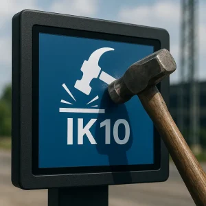
In automotive or rail applications, constant vibration combined with thermal cycles can loosen connectors. At +85°C, plastic housings expand at a different rate than the metal frame. We recommend using locking ZIF connectors and ensuring the Flexible Printed Circuit (FPC) has a “U-shape” slack to account for this physical expansion—a key detail in Wide Temperature TFT LCD Design that prevents micro-cracks in the copper traces over long-term deployment.To withstand physical stress, we utilize chemically strengthened cover glass that maintains its impact resistance across the entire operating temperature range.
Standard Industrial LCD Reliability Testing Checklist
When evaluating Industrial LCD Reliability Testing reports, look for benchmarks that align with the most demanding environmental standards. The following table represents the peak industry test conditions for true wide-temp modules:
| Test Item | Representative Condition* | Standard Duration/Cycle | Engineering Purpose |
|---|---|---|---|
| High Temp Storage | +85°C | 500 – 1000 Hours | Validates LC clearing point stability, polarizer aging, and adhesive integrity in high solar-loading environments. |
| Low Temp Start-up | -40°C | 24 Hours Soak | Ensures immediate Wide Temperature TFT LCD initialization and visual clarity in arctic climates. |
| Thermal Shock | -40°C ↔ +85°C | 100+ Cycles | The ultimate test for CTE (Coefficient of Thermal Expansion) mismatch between glass and housing. |
| H3 (High Temp/Humidity) | 60°C / 90% RH | 500+ Hours | Part of Industrial LCD Reliability Testing to check for electrochemical migration and LED lumen maintenance. |
*Note: Actual test conditions and durations are subject to the specific Wide Temperature TFT LCD part number and its corresponding technical datasheet. Always refer to the official specification for guaranteed ratings.
5. Integration FAQ: Common Wide Temperature TFT LCD Design Pitfalls
Q: Does my design actually need an ITO heater?
A: If your equipment stays off overnight in extremely cold regions (like Canada or Northern Europe), yes. If the device is 24/7 “Always On,” the self-heating of the backlight might keep the LC molecules functional, potentially saving costs on hardware during the Wide Temperature TFT LCD Design phase.
Q: Why is my screen dimming after 2 hours in the sun?
A: This is where your LCD Thermal Management Strategies need review. It is likely the LED driver’s over-temperature protection kicking in, or the LEDs themselves losing efficiency (Lumen depreciation). Improving the thermal bridge between the LED PCB and the chassis is the priority.
Q: How does Rocktech support Industrial LCD Reliability Testing?
A: We provide verified technical specifications and representative test data from our standard modules as a professional reference. For custom Wide Temperature TFT LCD Design, we offer technical consultations and mechanical reviews of your enclosure’s airflow and mounting, based on our extensive field experience in outdoor HMI and charging station projects.
Final Thoughts on Durable System Design
Beyond durability, all Rocktech modules strictly adhere to RoHS and REACH compliance, ensuring environmental safety for global deployment.Building a resilient system for harsh environments is a balance of high-quality components and thoughtful integration. While the Wide Temperature TFT LCD provides the foundation, its true field-life is determined by how the system handles the laws of thermodynamics through effective LCD Thermal Management Strategies.
Technological advancement in liquid crystal mixtures—specifically those with clearing points exceeding 110°C—is making solar-ready displays more accessible. By addressing Wide Temperature TFT LCD Design, cold-start sequencing, and rigorous Industrial LCD Reliability Testing early in the development cycle, engineering teams can build products that last a decade. The goal is to move beyond surviving the environment to thriving within it.